The global push for decarbonization has inevitably led the world to take a closer look at hydrogen. Hydrogen could be a good option for many sectors that cannot be easily electrified, such as aviation, steel or concrete production.
It can also speed up the cleaning of existing technologies such as gas turbines and combined cycles. Furthermore, renewable energy is intermittent and Green Hydrogen, generated by electrolysis using renewable energy, can be
used as a very effective means of energy storage. One of the key issues in future for large scale use of Hydrogen is Hydrogen transport. The US DOE has identified pipeline transport, either in gas or liquified form, as the most economical delivery option for hydrogen from the production to the demand centers.
In 2021, in a joint webinar with ANSYS, ADT looked at the design of a gas compressor and LH2 pump for hydrogen transport.

H2 Compressor Design
The basic design targets for the compressor were based on work by Witkowski et al [1], who conceptualized an 8 stage intercooled integrally geared compressor to achieve a 4:1 pressure ratio. The focus here was on the first stage compressor with a pressure ratio of 1.19 and flow rate of 2.8 kg/s, inlet pressure of 2MPa and temperature of 300K. By using TURBOdesign Pre, TURBOdesign1 and TURBOdesign Volute, the compressor shown in Figure 1 was designed. This
was found to achieve the target pressure ratio at high efficiency and meet the stress requirement using TI6AL4V.
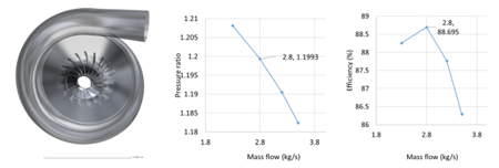
Fig. 1. H2 Compressor Stage design for Pipeline Transport and resulting performance.
LH2 Pump Design
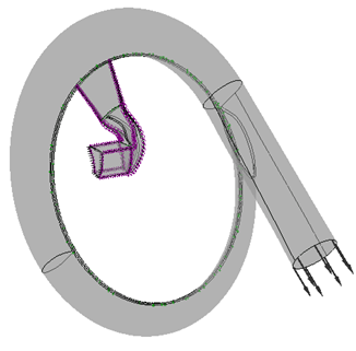
The main design inputs for the pump were assumed as follows: a stage head of 600 m and flow rate of 0.0467 m3/s, inlet pressure of 121257 Pa and temperature of 20K. For liquid hydrogen, this gives a mass flow rate of about 3 kg/s. Again TURBOdesign Pre, TURBOdesign1 and TURBOdesign Volute were used to design stage. As the vapour pressure of LH2 is relatively high at 95360 Pa, an inducer is necessary before the impeller in order to reduce the NPSHr. Two impellers were designed, one with full blades and another with splitter blades. Full stage CFD results on ANSYS CFX confirmed the duty point to be met in terms of head along with a slight margin to account for leakage losses and surface roughness not modelled in CFD. Further, a good matching between components ensured peak efficiency at the design flow rate,
see Figure 2.
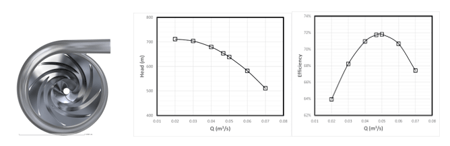
Fig. 2. LH2 Pipeline pump designed by TURBOdesign Suite.
References
1. Witkowski A, Rusin A, Majkut M, Stolecka K, Comprehensive analysis of hydrogen compression and pipeline transportation from thermodynamics and safety aspects, Energy 141 (2017) 2508-2518
Book a LIVE demo on the design of a turbomachinery application of your choice.
Our demo is tailored to your specific application and design challenges

Share This Post