The awareness in energy saving has continuously increased in the past decades, and this has led to higher energy efficiency requirement on HVAC applications. In the refrigeration and heat pump sectors, continuous efforts have been made to reduce the energy consumption to meet the new standards and regulations. It may be noted that the performance of the compressor is crucial to the vapor-compression system efficiency and operation.
Compared to reciprocating and screw compressors, centrifugal compressor has the advantage of high operational efficiency at full load and relatively compact size. It also enables the usage of the oil-free gas lubricated bearings, which do not have oil lubricant impairing the heat transfer efficiency of the heat exchanger, meaning that the system efficiency can be boosted to a higher level. Finally, centrifugal compressor also supports a wide range of capacities.
A major challenge in centrifugal compressors is the part load performance. Since a chiller can operate at less than peak load for more than 90% of the time, efficiency and stability at part load operation is very important to minimize the overall energy cost. With the help of variable frequency drive, centrifugal machines can operate at very low load conditions, and so the efficiency at part load condition is still a key area to be improved.
Compressor Design Process
The first step in the design of any compressor is to identify the required specific speed regime of the compressor. This will dictate the meridional shape and hence the general flow direction through the compressor. For example, a low specific speed compressor is likely to be a radial or centrifugal type, whereas a high specific speed compressor is likely to be of mixed flow or axial type.
From the required specific speed, we can identify the main flow phenomena and loss mechanisms dominant in that particular range (see Figure 1). For example, leakage and secondary flow effects are more dominant in lower ranges, whereas profile/shock losses and corner separation in diffusers take priority in the higher ranges.
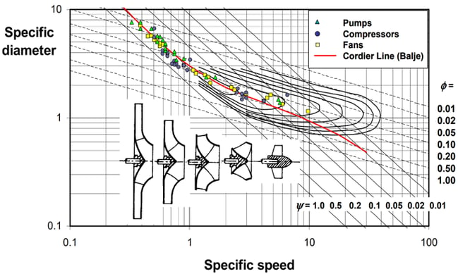
Figure 1: Cordier Diagram
From the information above we can use design tools and 3D CFD to investigate our compressor designs, what follows are a set of principal design guidelines based on the fluid dynamics considerations of reducing dominant flow losses for a given compressor. Over the years, ADT has been involved in thousands of compressor designs across all different specific speeds and applications, and has developed considerable fluid dynamic knowledge to systematically design high performance compressors using the compressor design software, TURBOdesign Suite.
Refrigeration Cycle Analysis and Meanline Design
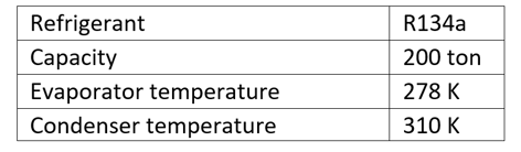
For the present chiller application, a single stage centrifugal compressor is designed consisting of an impeller, a vaneless diffuser and a volute. Here the refrigerant used is a widely used medium pressure refrigerant R134a and the chiller capacity is 200 ton. The design specification for the chiller cycle is shown in the table below:
In TURBOdesign Suite, a lookup gas table is adopted for real gas properties which can be read in from an .rgp format file created from the NIST database. A very useful feature is that once we have the relevant .rgp file in hand, then these real gas properties are taken into consideration throughout the design process, from refrigeration cycle analysis and meanline design through 3D blade design all the way to volute design, as shown in Figure 2.
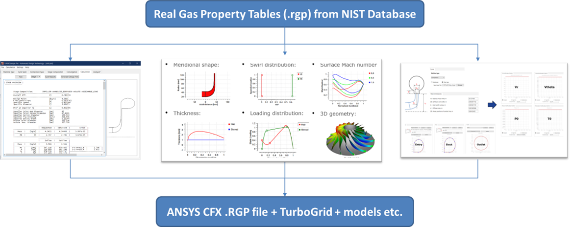
Figure 2: Real Gas Properties in TURBOdesign Suite
As Figure 3 shows, our meanline code TURBOdesign Pre has the capability to couple refrigeration cycle analysis with centrifugal compressor meanline design, and produces a summary of the cycle results along with the P-H and T-S diagram of the cycle.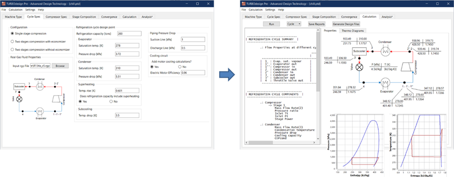
Figure 3: Refrigeration Cycle Analysis using TURBOdesign Pre
For the compressor, all that is needed is the rotational speed, and the rest of the duty point specifications such as the flow rate and pressure ratio is automatically taken from the cycle analysis. Once the coupled cycle and meanline calculation is complete, which takes just a few seconds, the compressor sizing and performance prediction are available as presented in Figure 4.
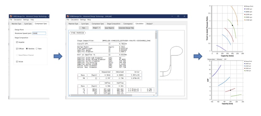
Figure 4: Meanline Design using TURBOdesign Pre
The compressor performance map is predicted at various rotational speeds, and it is also possible to have an evaluation of the chiller coefficient of performance (COP) at various RPMs. In fact, this information can help the designers to estimate the IPLV of the chiller at an early stage of the design. Along with the meridional shape, the meanline analysis also estimates the impeller work coefficient (rVt*) required to meet the pressure ratio target at the rating point. The work coefficient together with the meridional shape will be used in the next phase which is the 3D blade design of the impeller.
Below is the software demo of the Refrigeration Cycle Analysis and Meanline Design with TURBOdesign Pre
In another article, we demonstrate how to perform 3D design of the impeller, the vaneless diffuser and the volute, along with the CFD performance of the chiller compressor stage.

Book a LIVE demo on the design of a turbomachinery application of your choice.
Our demo is tailored to your specific application and design challenges


Share This Post