In another article, we cover the refrigeration cycle analysis and meanline design of a single stage centrifugal compressor for chiller application.
This article presents the 3D design of the chiller compressor stage including the impeller, the vaneless diffuser and the volute, and then confirms its high performance using CFD analysis. As noted earlier, the same real gas properties (.rgp) file that was used for the meanline design is also used for the 3D design of the impeller, the vaneless diffuser and the volute.
3D Blade Design of Impeller and Vaneless Diffuser
Figure 1 presents the setup for the impeller and vaneless diffuser in our 3D inverse design software TURBOdesign1, where the real gas properties, meridional shape and the default blade loading automatically come from the meanline code, and any thickness profile can be imposed to mitigate high stresses. Here the spanwise work distribution is free-vortex with zero swirl at the leading edge and a constant value from hub to shroud at the trailing edge. While normally this free-vortex distribution gives good performance, it is also possible to unload the hub at the expense of the shroud or vice versa.
With chiller compressors, as the operating point moves towards the low flow rate conditions, the diffusion on the impeller shroud suction surface increases and a separation can be triggered. Therefore, to avoid a small stall margin the shroud of the blade is slightly aft-loaded. However, the hub is more aft-loaded to avoid the hub separation and to minimize the loading difference between hub and shroud. This helps to suppress the secondary flow in the impeller passage and improves the leaving flow uniformity. Finally, the hub leading edge loading ensures that the throat area is sufficient for the peak efficiency point to stay close to the design condition, and then these inputs result in the 3D geometry of the impeller along with a smooth Mach number distribution over the entire blade surface.
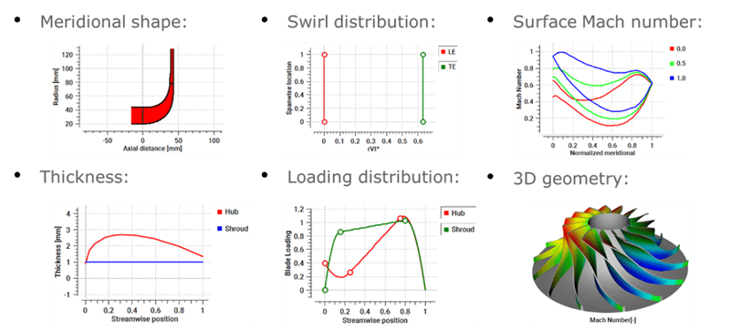
Figure 1: 3D blade design of impeller in TURBOdesign1
Here's a Software Demo of a Chiller Compressor of the Design of an Impeller with 3D Inverse Design
Volute Design
The meanline code also generates a volute report, and this information is used by TURBOdesign Volute to design the volute for the chiller compressor as shown in Figure 2. Together with the real gas properties and the main dimensions, it is possible to define the cross-section shapes at the entry, duct and outlet sections which are selected as asymmetric elliptic external in this case. The most important input is the boundary conditions at the volute inlet, i.e., the radial and tangential velocity components and the total pressure and temperature, because then TURBOdesign Volute runs a 2D inverse design code to produce the optimum cross-section area distribution for the given flow conditions at the exit of the vaneless diffuser.
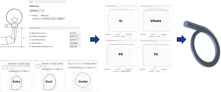
Figure 2: Input settings in TURBOdesign Volute
Here's a Software Demo of the Volute Design with TURBOdesign Volute
Stage CFD Analysis
Once all the components of the chiller compressor stage are ready, a stage CFD analysis is conducted to check the actual performance. The boundary conditions are chosen to match the inlet conditions and mass flow rate from the TURBOdesign1 case. Figure 3 illustrates the CFD setup, where ANSYS TurboGrid is used for the fully structured grids of the impeller and the vaneless diffuser, ANSYS Mesh for the hybrid mesh of the volute, and CFX for the flow analysis.
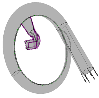
Figure 3: Chiller compressor stage CFD setup
Figure 4 reveals that when stage CFD runs are performed at three different flow rates about the design point, it is found that the peak impeller and stage efficiencies, along with the minimum volute loss happen near 100% design flow rate. This confirms that both the impeller throat and the volute are sized correctly for the design condition. Furthermore, the stage pressure ratio comfortably exceeds the target value from the meanline code.
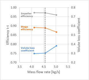
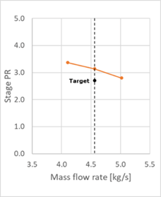
Figure 4: Chiller compressor stage performance maps
It is also interesting to note that the work coefficient (rVt*) from CFD matches very closely with what was specified in TURBOdesign1, with the actual blade loading plots in excellent agreement with the TURBOdesign1 prediction at the different spanwise locations, as confirmed in Figure 5.
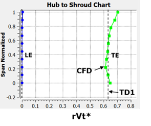
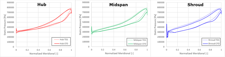
Figure 5: Impeller rVt* and blade loading comparison between TURBOdesign1 and CFD
Finally, Figure 6 displays the velocity vector plots in the radial and meridional views confirming good flow behaviour throughout the impeller and the vaneless diffuser.
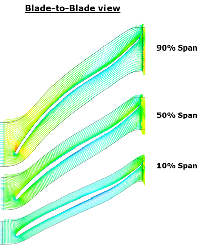
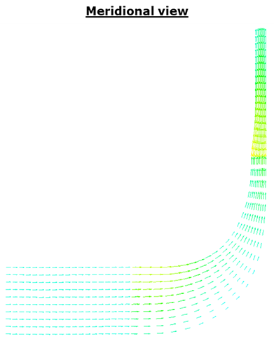
Figure 6: CFD velocity vector plots in the impeller and the vaneless diffuser
Concluding Remarks
In summary, this article series shows that centrifugal compressors are particularly suited for chiller applications and that it is possible to conduct simultaneous refrigeration cycle analysis and meanline design of a centrifugal compressor stage using our meanline code. It is also demonstrated how convenient it is to generate high performance impellers designed to handle refrigerants using 3D inverse design, which can later be optimized for full or part load operation. The rapid design of volutes optimized for the incoming refrigerant from the diffuser is also presented. Finally, the CFD results are proven to be in excellent agreement with the inverse design predictions, leading to a stage performance beyond expectations.

Book a LIVE demo on the design of a turbomachinery application of your choice.
Our demo is tailored to your specific application and design challenges


Share This Post