In another article, based on one of ADT’s technical papers that was presented at the European Turbomachinery Conference [1], we cover the baseline design of a tandem-blade centrifugal compressor along with its CFD performance, and conclude that there is scope for improvement in the design point efficiency
This article, based on the same paper, reveals how this was achieved through an optimisation methodology involving 3D inverse design method, DOE (Design of Experiments), Kriging RSM (Response Surface Model) and MOGA.
Design of Experiments
Figure 1 shows the inputs that are varied to create the design of experiments:
- rVt* ratio controls the extent of loading between inducer and exducer blades, where the baseline value is of 10% loading for the inducer
- The reference wrap angle for inducer trailing edge is linearly displaced from the baseline distribution with delta shroud at 0%
- The reference wrap angle for exducer trailing edge is linearly displaced with 0 wrap angle at the shroud for the baseline design
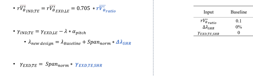
Figure 1: Input parameters for design of experiments
It is important to emphasize that the rVt* ratio and the circumferential shroud displacement are relevant inputs for tandem-blade designs and they can be easily controlled using the design methodology shown. Having the DOE inputs defined, 30 designs are sampled using the Latin Hypercube procedure, and CFD analysis is performed on them. From Figure 2, which shows how the rVt* ratio relates to the impeller total-to-total efficiency, it is immediately evident that an optimum value of rVt*ratio exists.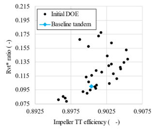
Figure 2: Data collected from DOE procedure: rVt* ratio against impeller efficiency
Response Surface Optimization
An optimization is performed on the response surface generated from the gathered data, in which the impeller total-to-total efficiency is maximized and the diffuser loss coefficient is minimized. Also, a pressure ratio constraint is imposed to maintained the value above 3.8. One optimized design is taken from the Pareto front for further analysis, as shown in Figure 3.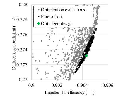
Figure 3: Optimization evaluations, including Pareto front, using Kriging response surface
The baseline and optimized tandem designs are compared in Figure 4:
- As seen previously, an ideal rVt* ratio is found, which is of around 13.9%
- The optimization tends to close the gap between the inducer and exducer, with a circumferential shroud displacement of -7%
- The wrap angle at exducer shroud is not seen to majorly influence efficiency with an optimized value of 0.283, thus staying very close to baseline
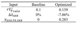
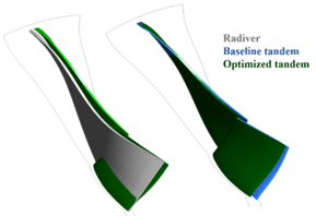
Figure 4: 3D geometry comparison between Radiver and Optimized tandem design (left); and between optimized and baseline tandem designs (right)
Optimized Design Performance
Figure 5 presents the results of CFD and FEA analyses performed on the optimized tandem design. Improved efficiency over the entire map can be observed in relation to the full blade Radiver compressor: 0.5 points at the design point and around 2 points at high flow rate. Although higher structural stresses are seen, an adjustment to inducer blade leading edge lean or hub thickness can easily fix this.
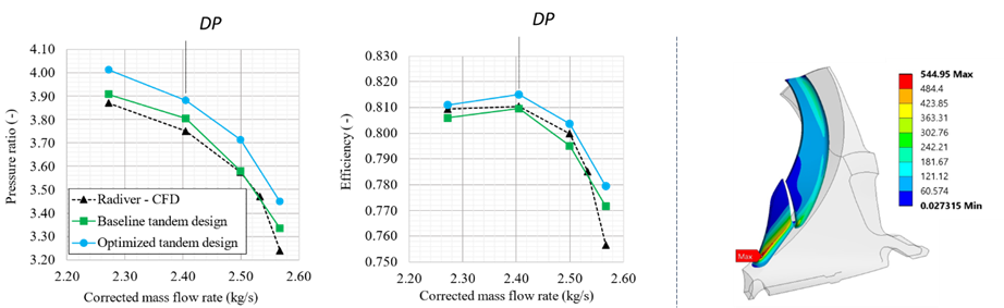
Figure 5: Tandem optimized design performance curves (left) and equivalent stress distribution (right)
Entropy Analysis
Having obtained an optimized tandem design, it is imperative to understand how the improved performance was obtained. For this, an entropy analysis is performed on the three designs studied, using a methodology presented in 2022 for centrifugal compressors with full blade configurations [2]. This method is based in decomposing the impeller flow domain into different zones, each zone associated with losses generated from a specific source such as shock, tip leakage, boundary layer and secondary flows. The entropy generation is then quantified in each domain, and its values can be compared between each design.
Figure 6 summarizes the entropy analysis results for each design:
- Shock and secondary flow losses can be seen to represent a small amount of the overall losses, and are relatively similar between all designs analysed
- Tip vortex entropy generation is reduced from full blade design to both the tandem blade baseline and optimized designs – representing the main loss reduction occurring due to the tandem arrangement
- Boundary layer losses are increased from full to tandem designs and are reduced from baseline tandem to optimized tandem designs – the optimization procedure reduced the boundary layer losses to improve efficiency
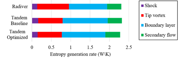
Figure 6: Entropy generation rate for different zones, for Radiver, baseline tandem and optimized design
From the 3D visualization in Figure 7, the tip vortex losses can be seen to reduce from Radiver to the optimized tandem design, due to an alleviation of the of the exducer loading. This is further confirmed by a smaller static entropy region for the tandem blade design at the outlet.
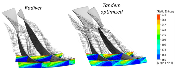
Figure 7: Tip leakage loss generation zone in Radiver compressor (left) and optimized tandem design (right)
Further observations can be made from the blade-to-blade entropy contour presented in Figure 8, where the wake from inducer trailing edge represents, as expected, a new source of loss. Although the boundary layer is reinitiated after inducer blade, the high velocities at exducer suction side lead to a rapid growth of the new boundary layer. The lower entropy generation of the tip vortex region can be seen here as well. Also, the higher wetted area of tandem designs directly leads to higher boundary layer losses.
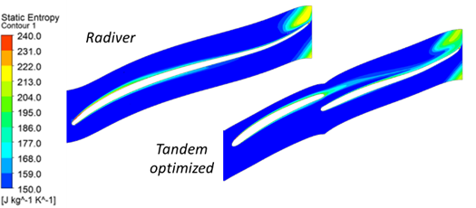
Figure 8: Comparison of blade-to-blade entropy contour at 50% spanwise position between Radiver (left) and optimized tandem design (right)
Conclusion
A tandem-blade design methodology was assembled, based on 3D inverse design, which allows easy control of the relevant design inputs. A baseline design was quickly obtained that met pressure ratio requirements, and the optimized design was obtained with improved efficiency and increased pressure ratio at all operating points. The entropy analysis made important revelations – the increase in boundary layer losses counteracted the improvement obtained by reduced leakage loss, and an optimization-based approach was required to achieve an improved design. Finally, it was shown that the loading distribution between inducer and exducer was a crucial parameter when designing compressors with this configuration – and that the design methodology assembled based on 3D inverse design allowed to easily control this distribution.
References
[1] Oliveira, R., Zhang, L., Zangeneh, M., “Tandem-blade Centrifugal Compressor Design and Optimization by means of 3D Inverse Design”, European Turbomachinery Conference, Budapest, 2023
[2] Zhang, L., Kritioti, L., Wang, P., Zhang, J., Zangeneh, M., “A Detailed Loss Analysis Methodology for Centrifugal Compressors”, Proceedings of ASME Turbo Expo 2021, Virtual, Online
Book a LIVE demo on the design of a turbomachinery application of your choice.
Our demo is tailored to your specific application and design challenges


Share This Post