Mixed-flow pumps are widely used at drainage pumping stations, power plants and in water-jet applications. When the specific speed is high, the design is considerably challenging since it is generally necessary to satisfy multiple performance objectives that are in relative trade-off. Furthermore, in addition to operating outside of the best efficiency region, the flow often approaches the impeller eye with low value of static pressure, leading the pump to operate under cavitating conditions.
In this article, we demonstrate how pump designers can exploit their knowledge of hydrodynamics to directly address specific flow phenomena in mixed-flow diffuser pumps using the inverse design approach. The design will be carried out in a parametric way where an initial pump configuration is generated first. Then, using the initial design as a baseline, the effect of five impeller design parameters will be investigated in a systematic way. Finally, the study will be used to determine the different, sometimes opposite, design settings which are required to maximize the suction performance and the hydrodynamic efficiency of the pump.
Problem Statement
In case of high specific speed mixed flow pumps, it is common practice to use fore-loaded impeller blades for its beneficial effects on efficiency, but it also aggravates cavitation levels in the impeller. Although cavitation can be addressed with modifications like leading edge sweep, they take a heavy toll on the blade stress. Therefore, this is evidently a complex multidisciplinary problem, and that is why conventional methods often involve large numbers of CFD and FEA runs in order to ensure that the appropriate trade-off is achieved, which consumes a lot of computational time and resources. This leads us to the problem statement:
- Is it possible to come up with a systematic study to separately evaluate the impact of these different design parameters on the various performance aspects of the pump?
- Is it possible to develop a rapid optimization methodology focused at suppressing the dominant losses but without adversely impacting the cavitation and stresses in your impeller?
This is what we aim to explore through this article series.
Pump Design Process
The first step in the design of any pump is to identify the required specific speed regime of the pump. This will dictate the meridional shape and hence the general flow direction through the pump. For example, a low specific speed pump is likely to be a radial or centrifugal type, whereas a high specific speed pump is likely to be of mixed flow or axial type.
From the required specific speed, we can identify the main flow phenomena and loss mechanisms dominant in that particular range as shown in Figure 1. From this information we can use design tools and 3D CFD to investigate our pump designs, and what follows is a set of principal design guidelines based on the fluid dynamics considerations of reducing dominant flow losses for a given impeller / diffuser.
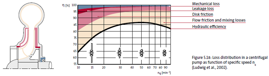
Figure 1: Loss breakdown in pumps.
Meanline Design of Mixed Flow Pump Stage
Figure 2 contains the specifications for the stage consists of an impeller and a volute, and based on this we can see that the design sits in the mixed flow region, and so this means that using these specs, it should be possible to design a mixed flow pump stage with a high efficiency level.
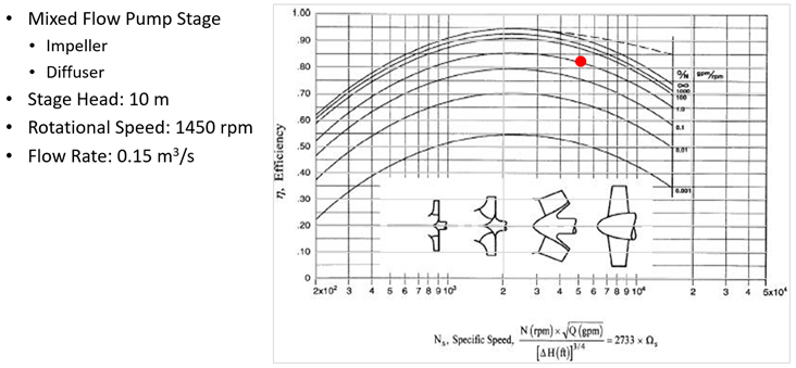
Figure 2: Mixed flow pump specifications and its position on specific speed chart.
Using the meanline code TURBOdesign Pre, it is very easy to enter the given specs and verify that it sits in the high efficiency mixed flow region of the specific speed diagram, and then it quickly generates the meridional shape in less than a second. As Figure 3 shows, it also provides a detailed report including the estimated stage performance and some important dimensions, as well as the required rVt* for the impeller and diffuser. This rVt* value is equivalent to the work coefficient and will be used for the 3D inverse design of these components in the next section.
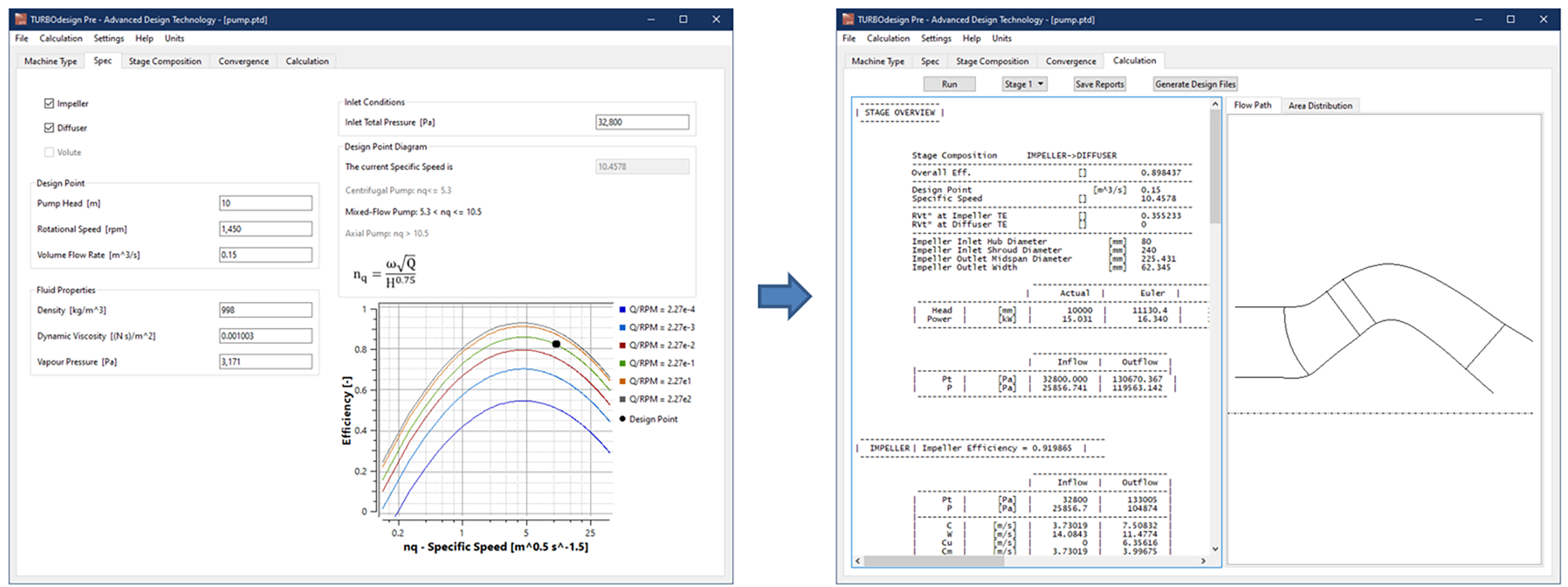
Figure 3: Meanline design of mixed flow pump stage in TURBOdesign Pre.
3D Blade Design of Impeller and Diffuser
Figure 4 presents the setup for the baseline impeller and diffuser in our 3D inverse design software TURBOdesign1, where the initial settings automatically come from the meanline code TURBOdesign Pre. It is also possible to impose your own custom thickness profiles which is very important for stress considerations. The spanwise work distribution for both components is free vortex, and so it has a constant value from hub to shroud. Furthermore, the rVt* at the diffuser leading edge is kept the same as the impeller trailing edge and this automatically ensures a good matching between them. The default loading distribution is fore-loaded for this baseline impeller and for the diffuser, it is fore-loaded at the hub and aft-loaded at the shroud. These inputs result in 3D geometries of the two components as seen alongside.
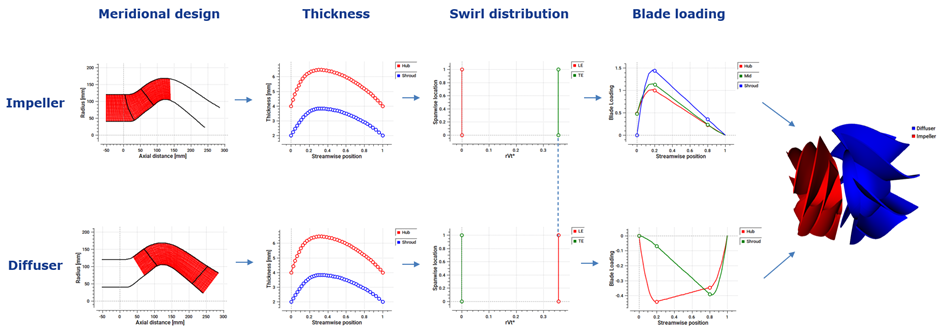
Figure 4: Mixed flow pump impeller and diffuser design in TURBOdesign1.
Some results from the inverse design are reported in Figure 5, which shows that the impeller diffusion ratio, which is the ratio of maximum surface velocity to the exit velocity, is sufficiently low to avoid flow separation. The bow ratio which is calculated from the wrap angles and dimensions at the leading edge is also shown, and its low value means that the blade is structurally safe. However, the blade surface minimum pressure is negative and this could possibly result in a cavitation scenario in this baseline impeller.
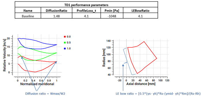
Figure 5: Impeller performance parameters in TURBOdesign1.
Baseline Stage CFD Analysis
Once all the components of the mixed flow pump stage are ready, a CFD analysis is run on the baseline stage to check the actual performance. As Figure 6 shows, ANSYS TurboGrid is used for the fully structured grids of the impeller and diffuser passages and CFX for the flow analysis. Also presented are the various CFD settings where the boundary conditions are chosen to match the TURBOdesign Pre case.
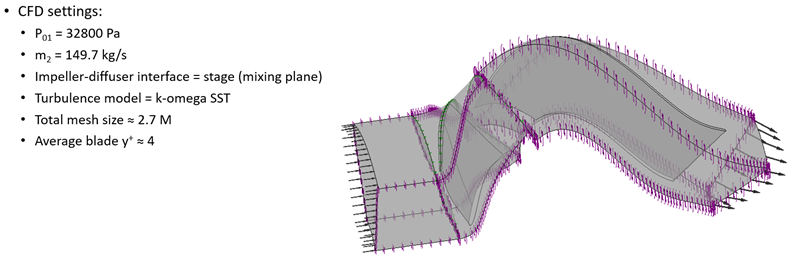
Figure 6: Mixed flow pump stage CFD setup.
Figure 7 reports the CFD results for the baseline stage which indicate that the peak impeller and stage efficiencies happen at design flow which means that the impeller throat is sized correctly. Moreover, the minimum NPSHR is also at design flow, which means that the best suction point is also close to the design point. In terms of the stage head, it exceeds the target of 10 m and blade-to-blade vectors confirm that flow behaviour is good throughout the pump.
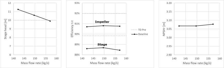
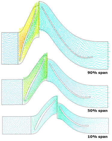
Figure 7: Mixed flow pump CFD performance.
However, as predicted by the inverse design results, the blade loading plots from CFD presented in Figure 8 are also going under the vapour pressure level, confirming the potential risk of cavitation inception in this baseline impeller.
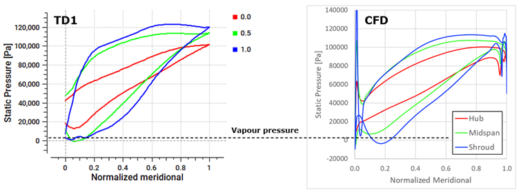
Figure 8: Mixed flow pump impeller CFD blade loading (baseline).
Therefore, in a parametric analysis which follows, five impeller design parameters will be systematically varied in TURBOdesign1 in order to assess their impact on the pump hydrodynamic and suction performance.
Parametric Study 1 – Blade Loading
In the first study, two impeller configurations are generated, one with a mid-loaded distribution and another with an aft-loaded distribution, which is in fact very easy to do with inverse design as shown in Figure 9. Also included are the resulting blade loading plots from CFD, which clearly show that aft-loading the blade shifts the peak of the loading toward the rear part of the blade and reduces the pressure valley, such that it rises above the vapour pressure line.
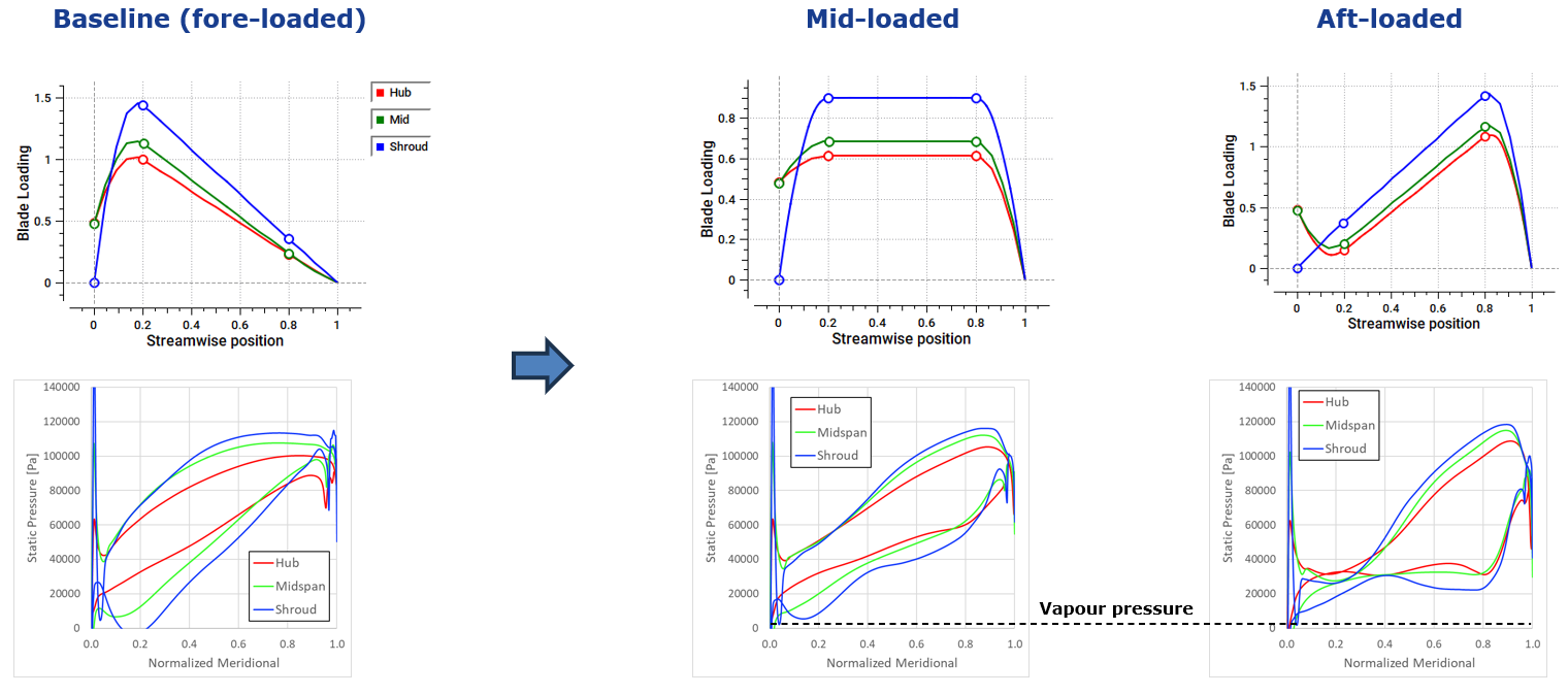
Figure 9: CFD blade loading of mid-loaded and aft-loaded mixed flow pump impeller.
Among other results, Figure 10 reveals that the minimum pressure in TURBOdesign1 goes up which translates to lower NPSHR levels, or an improved suction performance in CFD with aft-loading. However, the impeller profile loss increases, leading to a drop in the stage head and efficiency in the CFD results.
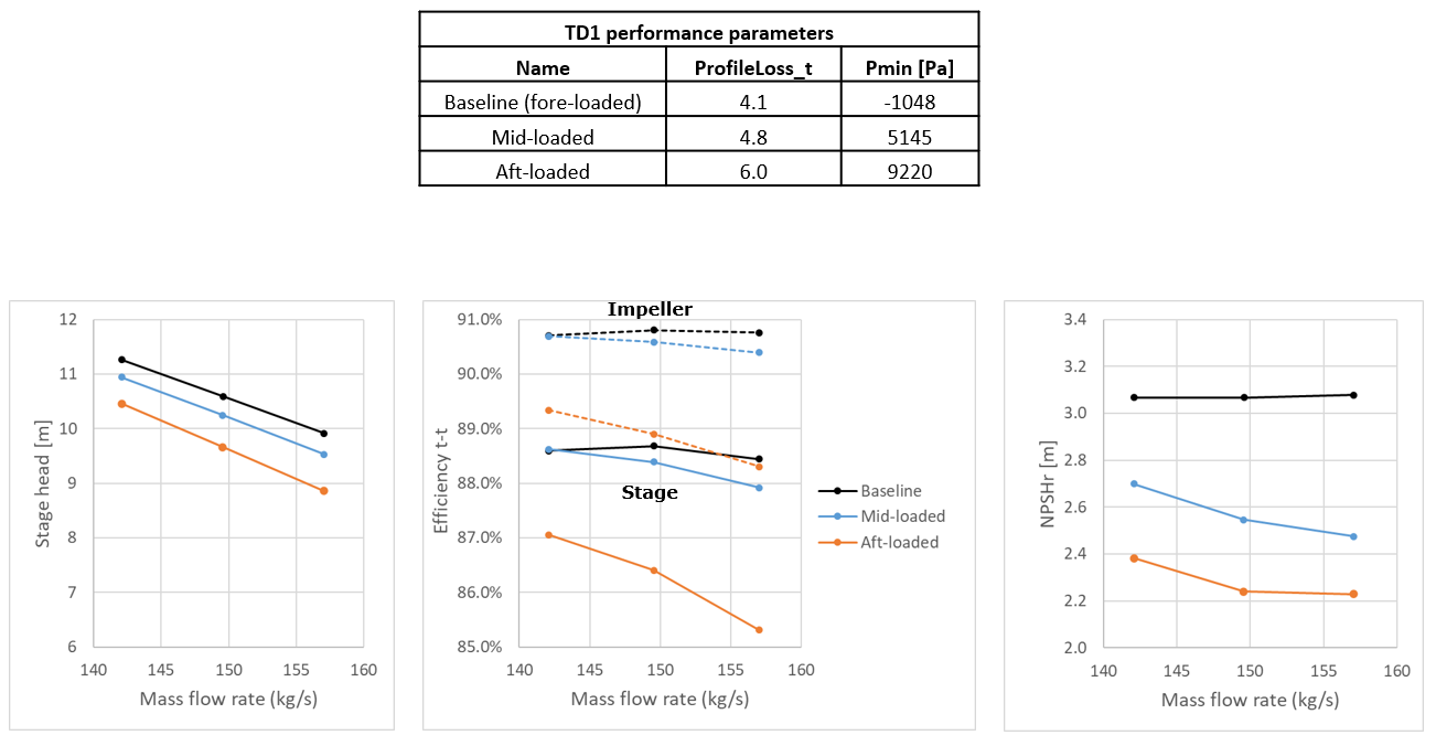
Figure 10: Performance comparison of the mid-loaded and aft-loaded impeller.
Parametric Study 2 – Stacking
In the second study, two stacking conditions are used near the impeller trailing edge, one with a forward stacking where the shroud leads the hub in the direction of rotation, and another with an opposite or a backward stacking condition as shown in Figure 11. Forward stacking increases the mass flow through the shroud leading to a higher pressure jump and therefore a deepening of the pressure valley here, whereas backward stacking has the opposite effect which means a reduction in the pressure valley.
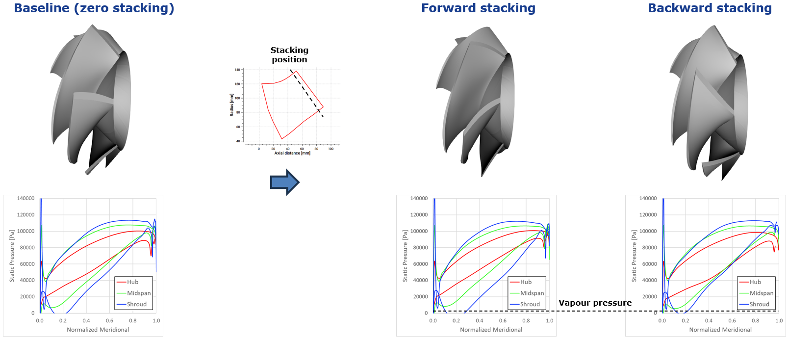
Figure 11: CFD blade loading of mixed flow pump impeller with forward and backward stacking.
This can also be observed in the CFD performance maps of Figure 12, where the NPSHR has improved due to backward stacking, but minimal impact is observed on the pump head and efficiency.
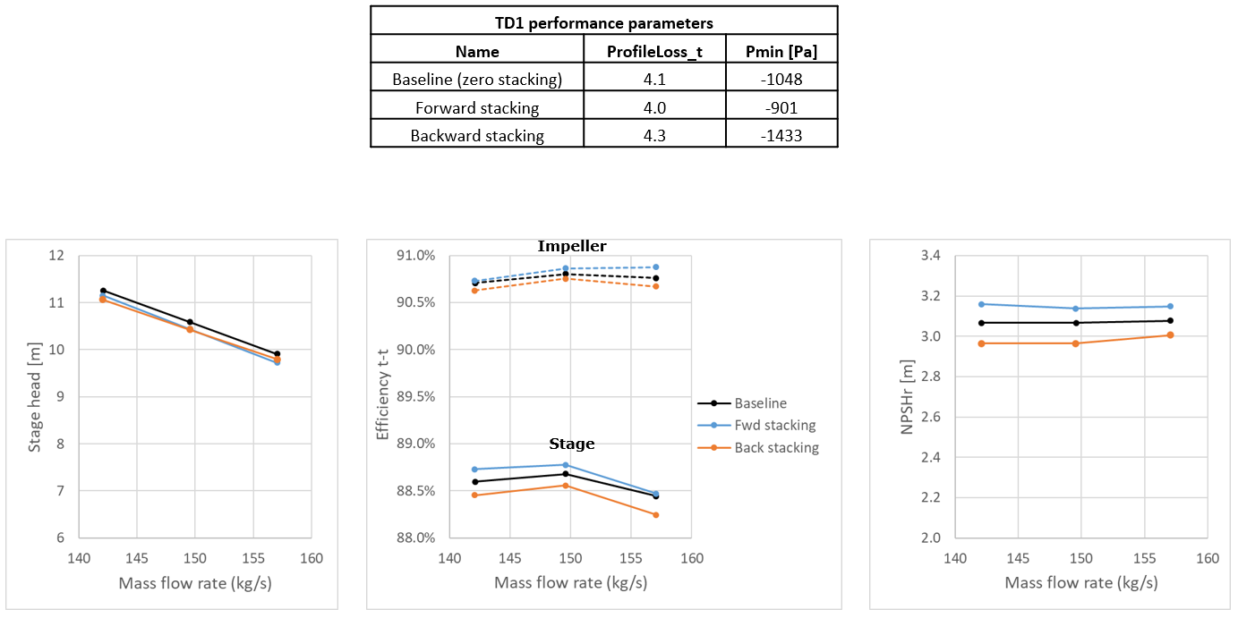
Figure 12: Performance comparison of the forward and backward stacked impeller.
Parametric Study 3 – Leading Edge Sweep
In the third study, two impeller configurations are generated with increasing forward sweep at the impeller leading edge as shown in Figure 13. The resulting longer shroud section leads to a lower pressure jump across it and hence a reduction in the pressure valley here.
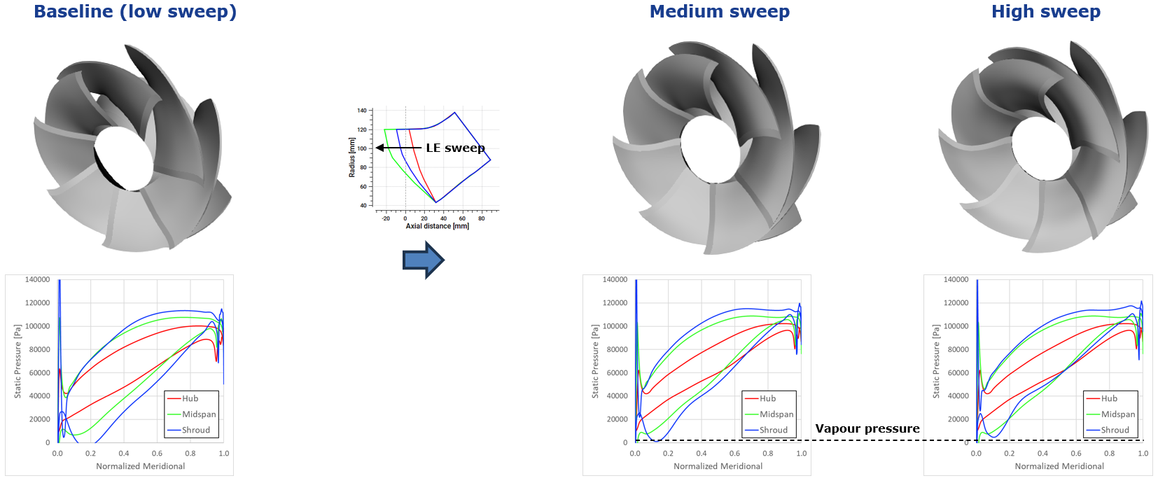
Figure 13: CFD blade loading of mixed flow pump impeller with medium and high leading-edge sweep.
In terms of other results reported in Figure 14, so far as the medium sweep configuration is concerned, there is an improvement in the NPSHR without any compromise on efficiency. However, the larger wetted area of the high sweep configuration leads to a higher profile loss and a corresponding drop in efficiency. Furthermore, high sweep also pushes the bow ratio to unacceptable levels making the pump operation structurally unsafe.
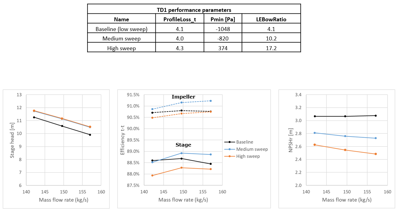
Figure 14: Performance comparison of the medium and high sweep impeller.
Parametric Study 4 – Impeller Exit Hub Radius
In the fourth study, the impeller exit hub radius is varied while keeping the maximum pump diameter fixed by considerations on the weight and size of the pump as shown in Figure 15. Since the changes in meridional shape are mostly in the rear part of the impeller, the blade pressure distribution in the front part remains similar and therefore, the cavitation performance is not influenced much.
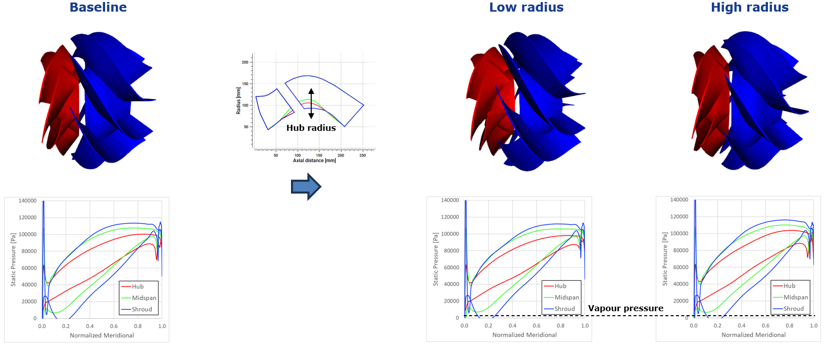
Figure 15: CFD blade loading of mixed flow pump impeller with low and high exit hub radius.
However, in terms of efficiency, the high radius case has some advantages. For example, a higher percentage of the work is performed by centrifugal forces in this case. Furthermore, the smaller impeller exit delivers a more axial flow to the downstream diffuser, and so the flow turning required by the diffuser is reduced leading to a smaller secondary flow development. All this results in higher stage efficiency and head for the high radius case as shown in Figure 16.
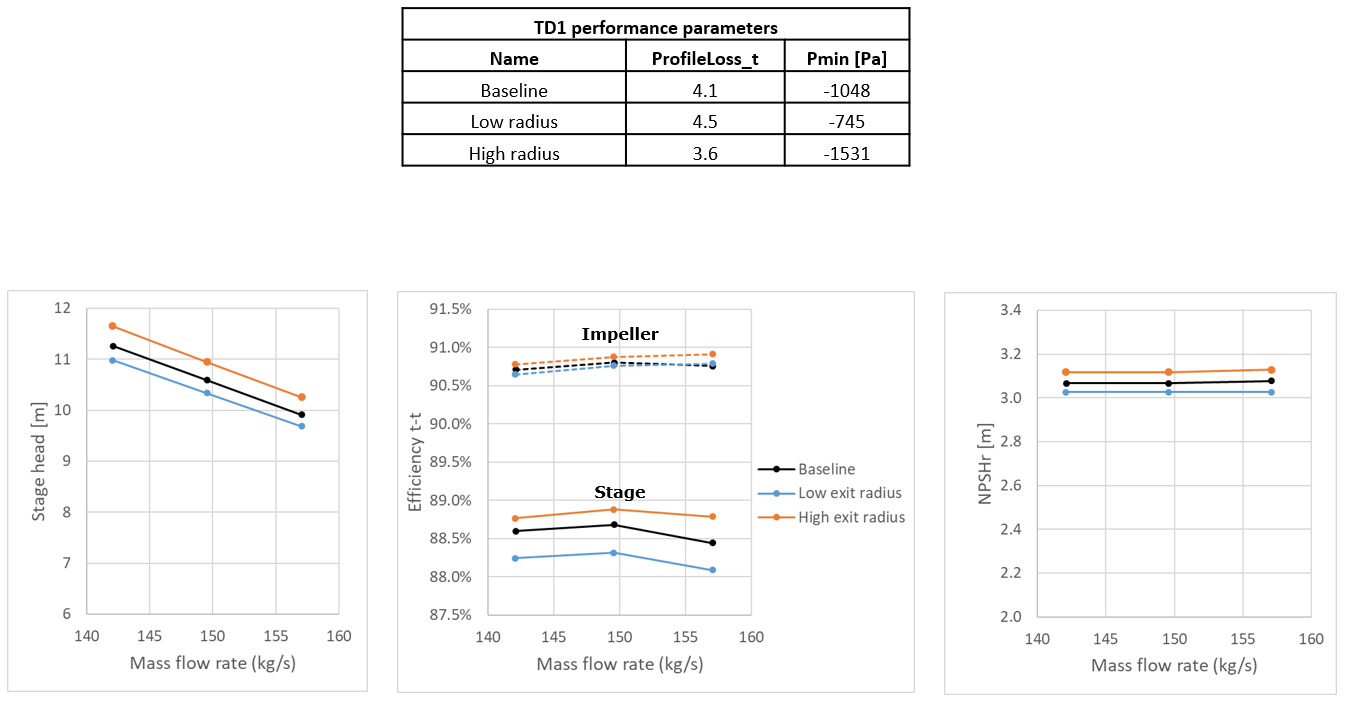
Figure 16: Performance comparison of the low and high exit hub radius impeller.
Parametric Study 5 – Impeller Exit Vortex Distribution
In the final study, the impeller work profile is varied from the original free-vortex distribution. In the first configuration, the specific work decreases from hub to shroud whereas in the second, it increases from the hub to shroud. And with TD1, it’s very easy to apply the same work distribution on the diffuser to match the impeller for each case. But in the CFD results, the blade loading changes are mostly seen towards the rear of the impeller, and so there isn’t much improvement in the pressure valley.
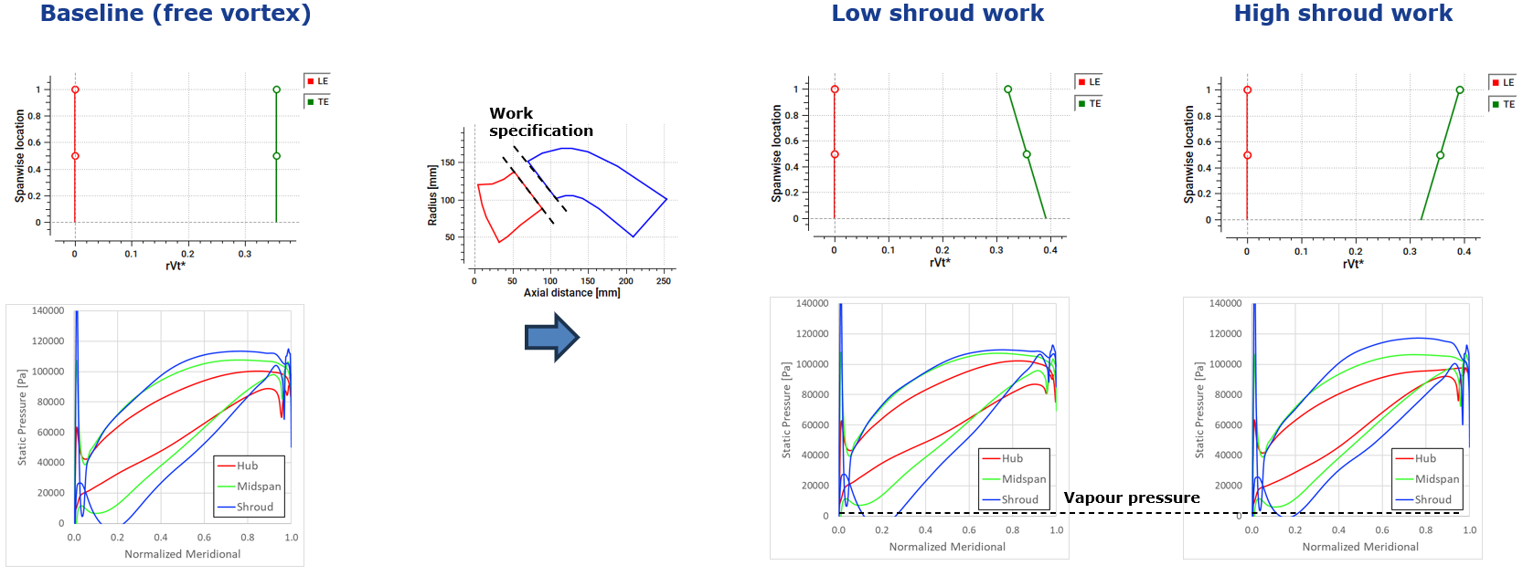
Figure 17: CFD blade loading of mixed flow pump impeller with low and high shroud work
Another interesting result is that both configurations present a drop in efficiency, and the reason is that the hub is characterized by a considerably smaller radius than the shroud section and so, increasing the hub specific work in either the impeller or diffuser requires a much larger flow turning there, with consequent increase in boundary layer losses.
Figure 18: Performance comparison of the low and high shroud work impeller
Therefore, it is evident from this parametric analysis that there is a trade-off when it comes to the hydrodynamic, suction, and mechanical aspects of the impeller. In the second part of this article, we demonstrate a selection of the optimal combination of these design parameters for maximizing cavitation performance, while guaranteeing a high efficiency level, together with mechanical and vibrational constraints. Additionally, we reveal how the efficiency of this redesigned impeller can be pushed even further through the use of automatic optimization with inverse design without adversely impacting the stress and cavitation aspects.


Share This Post