Blade loading is the single most important aerodynamic design parameter in turbomachinery blades. It defines the amount of work made or extracted by the blade and the distribution of such work from hub to tip/shroud. Most designers would be familiar with the representation of blade loading typically used to post-process blade design in CFD software such as the one presented below from Ansys CFX turbo tools.
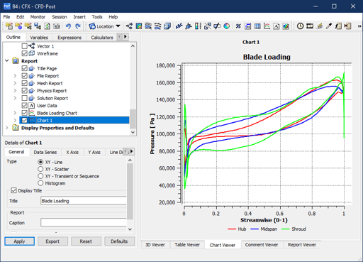
Fig. 1. Blade loading of an industrial centrifugal compressor pressure ratio 2:1.
Analyzing the blade loading of a given blade is a mandatory step for all design activities. It can present the user with valuable information on the localized blade performance and show potential issues affecting the blade efficiency. Some of such issues are for examples shown below:
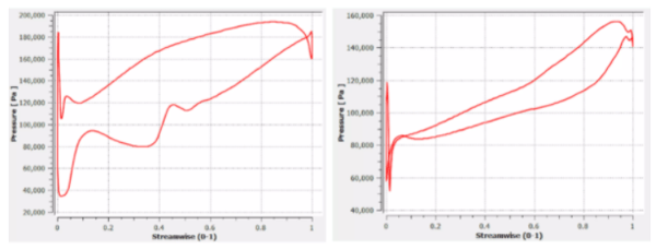
(Left) Shocks on suction surface; (Right) Negative leading edge incidence.
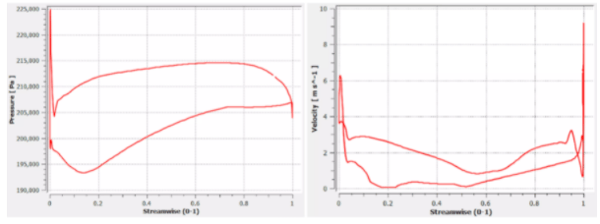
(Left) High suction side diffusion; (Right) Double dip on pressure surface.
In typical design activities, the task for all designers is to modify the blade so that the blade loading is smooth and doesn’t show any of the effects shown in the examples above, but how is this done?
There are two mainstream blade design approaches: direct and inverse methods.
In the direct method, for centrifugal machines, the blade is designed starting from the leading edge and trailing edge values generally derived from 1D / Meanline design tools, or assumed by experience and past designs, then specifying the blade angle distribution from the fixed value at the leading edge, to the fixed value at trailing edge. The 1D/meanline codes generally fix the LE/TE values in an attempt to fix somehow the machine-specific work, such as the compressor pressure ratio, so in most cases, designers use a number of splines and control points to connect the LE/TE values in what is generally a smooth distribution. This procedure is repeated for 2 or more spanwise sections from hub to tip/shroud in order to represent a 3D blade, as shown in Fig. 2.
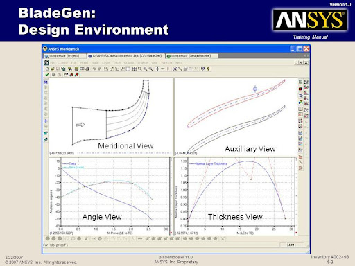
Fig. 2. Direct design approach as presented in Ansys BladeGen with user input of blade angle distribution.
Inverse Design Method
In the Inverse Design method, the blade loading is an actual input to the blade design for both axial and radial turbomachinery. The solver calculates the blade geometry to satisfy the designer's inputs to generate a unique 3D blade solution. This directly controls the blade's aerodynamic performance and provides a more logical design approach.
Some early inverse design methods specified the surface pressure distribution on both the suction and pressure side of the blade along the different spanwise sections. However, these methods failed to provide a robust and consistent approach to design as the actual spanwise work is not known before the specification.
A different inverse design approach was developed by Advanced Design technology and implemented in the commercial turbomachinery blade design software TURBOdesign1; this new approach decoupled the spanwise and streamwise blade loading alongside the blade thickness to provide a robust, consistent and intuitive turbomachinery design environment.
The blade loading is hereby divided into the spanwise work distribution (rVt) and the streamwise loading.
Spanwise Work Distribution
The Spanwise rVt*, non-dimensionalised value of rVt [rVt* = rVt / (Rref * Uref)], relates to the Euler equation:
And directly specifies the amount of work done or extracted by the blade row. This is specified firstly at the Leading Edge of the blade, an amount of 0 rVt* for example indicating the flow is fully axial, and there is no swirl coming into the blade, and at the trailing edge of the blade. With this simple step, the blade will always provide the required Head for Pumps, Pressure Raise / Ratio for Fans and Compressors, hence always satisfying the turbomachinery basic requirements at the nominal design point.
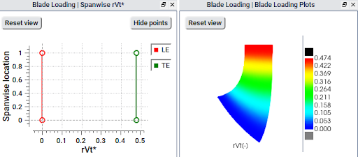
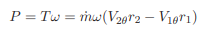
Fig. 3. Typical Spanwise rVt* distribution and rVt* contours on the meridional plane for a centrifugal pump or compressor impeller featuring zero swirls coming in at the leading edge and a free-vortex distribution.
In most direct design procedures, users have limited controls over the spanwise work distribution that generally considers the average amount of work based on 1D methods and leading edge / trailing edge blade angle specification, whereas, with the inverse design approach, users can carefully optimize the spanwise work distribution from hub to shroud, this essential to achieve very high-efficiency designs.
The examples reported below show typical rVt* distributions for two other machines, an axial fan and a radial inflow turbine. You can read more about Optimum Blade Loading for Turbomachinery on our Knowledge Hub:

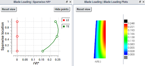
Fig. 4. Typical Spanwise rVt* distribution and rVt* contours on the meridional plane for an axial fan with reduced loading at the hub and tip of the blade; this helps reduce the recirculation in the hub region and also the tip leakage losses while diffusing the blade to blade vortex which is also beneficial to reduce noise. This Spanwise rVt* distribution is generally applicable to all axial propeller fans.
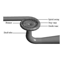
Fig. 4. Typical Spanwise rVt* distribution and rVt* contours on the meridional plane for a radial inflow turbine, featuring a free-vortex flow distribution at the runner inlet and almost zero swirls at the runner outlet. The value of rVt* is chosen to produce the available head at the runner inlet.
Streamwise Loading Distribution
The next step in the design is to specify the Streamwise Loading, or the distribution of work from the Leading Edge to the Trailing Edge of the blade at the hub, shroud and any section in between.
In the commercial turbomachinery blade design software TURBOdesign1 the streamwise blade loading is specified using a three-segment method composed of a parabolic section from the Leading Edge to a point NC, a linear section from NC to a second point ND and a parabolic section from ND to the Trailing Edge. The Meridional position of the points NC and ND can be controlled by the user along with the linear section's inclination slope to control the blade's fore-loading and aft-loading, as shown later. At the Trailing Edge, the loading must always be zero in order to satisfy the Kutta condition. In contrast, at the Leading Edge, zero loading is equivalent to zero incidence and users can define positive or negative loading to control the blade incidence.
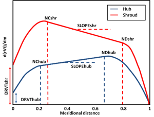
Fig. 5. Streamwise Blade Loading parameterization in commercial turbomachinery design software TURBOdesign1.
Most designers will be familiar with the terminology of fore-loading and aft-loading the blade; the aerodynamic benefits of using such practices in specific turbomachinery applications is well known and documented in the literature.
However, the know-how associated with how to achieve such blade loading is kept as a most guarded secret by most companies and only developed over many years of design experience. In fact, it is not atypical for turbomachinery manufacturers to train design engineers for 2 to 4 years in CFD before giving them actual design tasks.
With the Inverse Design methodology, the blade loading is specified. As long as engineers understand the basic aerodynamic design principles of the blade they are designing, it is practically immediate to achieve a specific loading distribution.
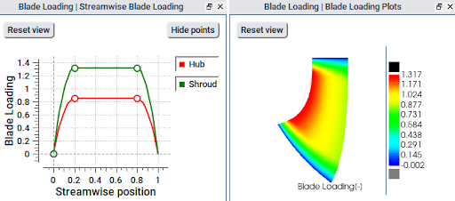
Fig. 6. Streamwise Loading distribution and loading contours at the hub and shroud of a centrifugal impeller; the picture shows a mid-loaded distribution at both hub and shroud of the blade.
The picture above shows a mid-loaded configuration; this means that most of the work is carried out towards the mid of the blade, but more interesting and aerodynamically efficient distributions can be specified.
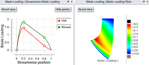
Fig. 7. Fore-Loaded Streamwise Blade Loading and loading contours on the meridional plane for a centrifugal pump impeller; this loading configuration has generally been found to reduce profile losses on the blade and generate high-efficiency axial and mixed-flow pumps.
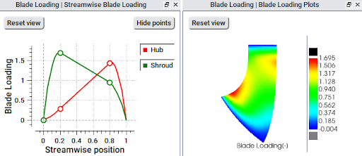
Fig. 8. Streamwise Blade Loading featuring a Fore-Loaded Shroud and an Aft-Loaded Hub; this complex blade loading distribution has been found to effectively control the generation of secondary flows in centrifugal compressors and pump impellers.
One of the most critical aspects of a robust turbomachinery design environment is to allow designers to explore the design space without losing control over the blade specifications; for example, a recurring problem with Direct Design is that changing blade angle distribution affects the impeller head/pressure ratio or pressure rise. In the Inverse Design approach, the distribution of Streamwise Loading is input as a shape function so in all examples above as the distribution changes, the area underneath the loading curve (drvt/dm) is automatically scaled to match the Spanwise rVt* specified in the previous step. Every design performed in these steps will automatically satisfy the required Euler Head / Pressure Ratio / Pressure Raise of the blade row.
Conclusion
Blade loading is the most important consideration in the design of turbomachinery blades. Therefore, compared to the direct method, the inverse design method makes for a more logical approach towards this by directly taking control of blade loading to achieve a specific outcome from a blade.
The added benefit is that the resulting blade always satisfies the duty point requirements at the nominal design point. This means that all that is required from the engineers is an understanding of the basic aerodynamic design principles of the blade they are designing.
Related Articles:
What is the optimum blade loading for?

Book a LIVE demo on the design of a turbomachinery application of your choice.
Our demo is tailored to your specific application and design challenges


Share This Post