In the first part of this article on the design and analysis of a high specific speed mixed flow pump, we showed that there is a complex trade-off when it comes to the hydrodynamic, suction, and mechanical aspects of the impeller.
In this second part, we demonstrate a selection of the optimal combination of these design parameters for obtaining the desired trade-off. Additionally, we reveal how the performance of this redesigned impeller can be enhanced even further through the use of automatic optimization with inverse design.
Parametric Redesign
Figure 1 table shows a results summary of the parametric study from the previous article. Based on this, the following design choices are made:
- Regarding blade loading, aft-loading clearly has conflicting impacts on efficiency and cavitation. So, the hub and midspan sections, which are less critical for cavitation, are fore-loaded to maximize efficiency, whereas the shroud section is fore-loaded from 40% of the chord to the trailing edge, while its inlet region is unloaded to reduce the critical pressure drop on the shroud suction side.
- In terms of stacking, backward stacking is selected which is good for cavitation but does not compromise on efficiency.
- Medium leading-edge sweep is preferable which is beneficial for both efficiency and cavitation
- High exit hub radius is used which raises the efficiency but without a cost on cavitation.
- Work distribution is left unchanged to free-vortex, since neither configuration gives a definitive advantage.
Clearly, the redesigned impeller geometry is very different from the baseline, as shown alongside.
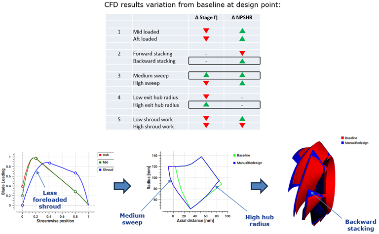
Figure 1: Parameter selection for impeller redesign.
The performance of the redesigned impeller is reported in Figure 2. As far as the inverse design parameters are concerned, there is a considerable improvement in the minimum pressure without any significant adverse impact on the profile loss or the bow ratio, thus giving a guarantee of structural robustness. In terms of CFD results, the design point stage head is higher by nearly 8% and both impeller and stage efficiencies are raised by about 0.5% point. The NPSHR is reduced by almost 0.5 m, and shroud blade loading plots confirm that the pressure stays above the critical level implying that a cavitation scenario is completely avoided in the redesigned impeller.
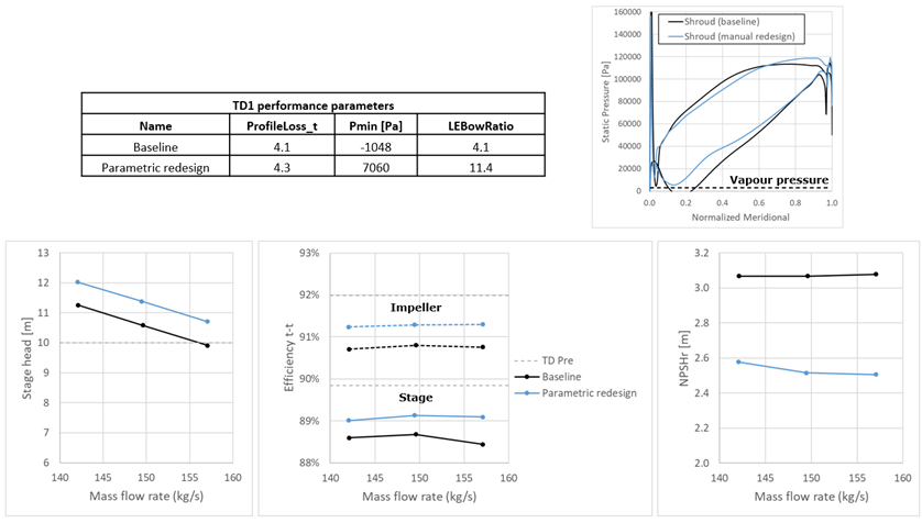
Figure 2: CFD performance maps of the parametrically redesigned mixed flow pump
In the next section, we will see how the performance of this redesigned impeller can be enhanced even more through the use of automatic optimization with inverse design.
Optimization Workflow
Figure 3 displays the workflow used by the automatic optimization, where the blade loading parameters are used to generate the blade shape in TURBOdesign1, and then the resulting performance parameters are fed into TURBOdesign Optima which basically applies the reactive response surface (RRS) algorithm to drive the solution towards the optimum design.
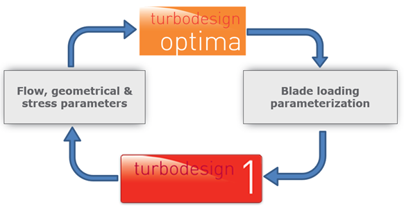
Figure 3: Workflow used in automatic optimization of mixed flow pump impeller
Optimization Setup
The optimization process starts by selecting the target case which is the parametrically redesigned impeller, and specifying the range of variation for the inputs, which are the streamwise loading parameters as reported in Figure 4. It may be noted that since the optimal leading-edge sweep, exit hub radius and stacking have already been identified through the parametric study, these are not varied in this optimization.
The constraints imposed on the optimizer are as follows:
- throat is constrained to ± 10% to confine the best efficiency point
- overall diffusion ratio is limited to avoid flow separation
- leading-edge bow ratio to limit the blade stress
Finally, the optimization objectives are selected to:
- minimize the total profile loss to increase the impeller efficiency
- maximize the minimum pressure in order to control cavitation
In this way, it is ensured that blade integrity and suction behaviour are not compromised in the process of improving its hydrodynamic performance.
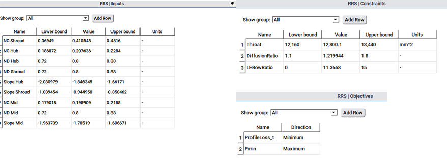
Figure 4: Inputs, constraints, and objectives used in automatic optimization
Optimization Results
Once the RRS optimization run is complete, which is very fast and only takes about 5 minutes or so on a single core machine, the design candidates can be seen on a scatter plot of the two objectives, the profile loss on the X axis and the minimum pressure on the Y axis as shown in Figure 5. The position of the parametrically redesigned impeller relative to the candidates may also be noted.
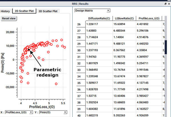
Figure 5: Scatter plot between profile loss and minimum pressure of candidate designs
Next as Figure 6 shows, we can choose to see the Pareto front of optimum designs from which we can pick and analyse any design of interest. For the present work, we select a design which has a much higher minimum pressure for the same profile loss, and so we use this design for further analysis and for comparison with the redesigned impeller.
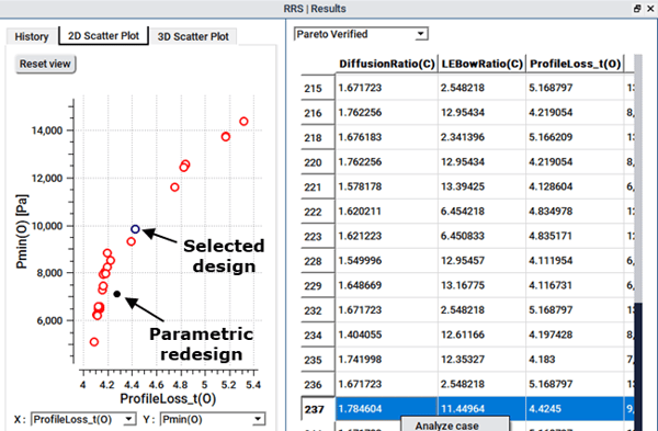
Figure 6: Pareto front of optimum designs with the selected design
Optimized Impeller Performance
Figure 7 reveals what changed as a result of the optimization. Compared to the redesigned impeller, the optimizer recommends a complex streamwise loading as it attempts to increase the minimum pressure while keeping the profile loss down. The resulting CFD blade loading plot confirms that there is no risk of cavitation in the optimized impeller.
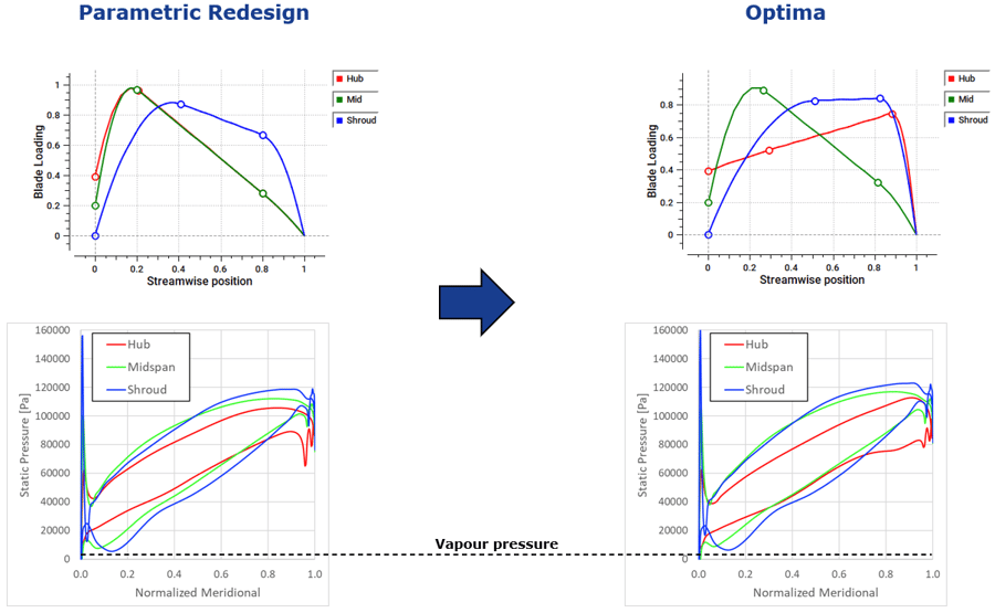
Figure 7: Blade loading comparison between redesigned and optimized impeller
Looking further into more results in Figure 8, it is interesting to see the effect on the inverse design parameters where the increase in minimum pressure from the optimization does not adversely impact the profile loss or bow ratio. When stage CFD is repeated with the optimized impeller, what we find is that the design point stage efficiency rises further and is now 1 percentage point above the baseline pump. The pump head has also advanced further and is now 15% higher than the baseline pump. Moreover, the NPSHR shows a further improvement and is now 0.6 m below the baseline pump value.
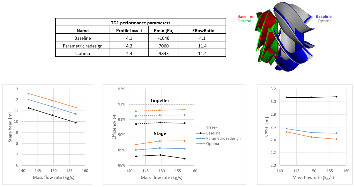
Figure 8: CFD performance maps of the optimized mixed flow pump
Cavitation CFD Analysis
In order to confirm the improvement in suction performance, the baseline and optimized pumps are also analyzed by means of CFD analysis with the cavitation model. This is performed at the design operating condition design mass flow rate and operating inlet total pressure, and Figure 9 shows the cavitating regions based on the vapor volume fraction. Here the impeller is oriented so that the suction side of the blade is visible, and clearly the optimized design works under nearly cavitation-free conditions at the design point, while the baseline presents a cavitating region in the shroud area corresponding to the location of the pressure valley. Therefore, with respect to the baseline, the optimized design presents superior cavitation performance in agreement with the predictions based on the CFD evaluation of the NPSHR shown earlier.
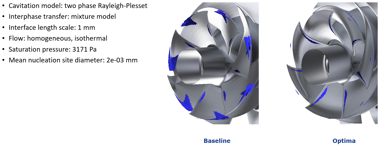
Figure 9: Cavitation CFD analysis results for the baseline and optimized mixed flow pump
In this way, the parametric redesign followed by the rapid optimization methodology is able to simultaneously improve the pump hydrodynamic and suction performance without compromising on its structural integrity. Only a few CFD runs are required to achieve and verify the improvements:
1 baseline + 10 parametric study + 1 parametric redesign + 1 optimized + 2 cavitation = 15 runs
Conclusion
High specific speed mixed flow pumps typically present a complex trade-off between the hydrodynamic, suction and structural aspects of the impeller. The inverse design method makes it possible to separate these effects through a quick and easy parametric study, based on which the following design guidelines can be established:
- Hub to mid-span should be fore-loaded to improve efficiency, whereas shroud should be relatively less fore-loaded to suppress cavitation
- Medium leading-edge sweep improves both efficiency and suction performance
- High impeller exit hub radius improves efficiency
- Backward trailing-edge stacking reduces cavitation
These can be used to redesign the impeller aimed at maximizing cavitation performance, while guaranteeing a high efficiency level, together with mechanical and vibrational constraints.
Additionally, using automatic optimization on the streamwise loading parameters, it is possible to further optimize the impeller and achieve this trade-off in a matter of minutes. Moreover, this methodology involves very less computational resources in terms of CFD runs compared to conventional design methods. Our experience has shown that the choice of optimum loading for controlling profile loss or cavitation has generality and can be applied to other similar applications. For example, we find that for profile loss control, the type of loading that we use for pumps is applicable to all types of pumps, centrifugal and axial and regardless of the pump speed or size.

Book a LIVE demo on the design of a turbomachinery application of your choice.
Our demo is tailored to your specific application and design challenges


Share This Post