Across the specific speed range, compressors are subject to various flow phenomena and loss mechanisms which are dominant in that particular range. For example, leakage and secondary flow effects are more dominant in lower ranges, whereas profile/shock losses and corner separation in diffusers take priority in the higher ranges. In this article, we focus on shocks and how to come up with a set of optimal design guidelines to control this particular loss mechanism in a compressor.
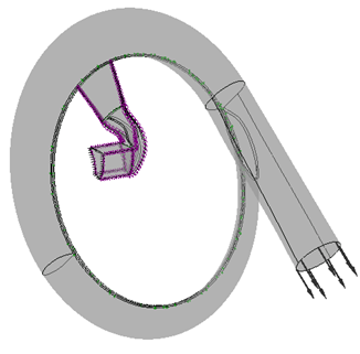
Generally in transonic compressors, even though secondary flows can be present, shock losses are found to be the dominant source of loss. Therefore, the type of loading specified needs to be focused on controlling these shock losses. The subject covered here is a 4.5:1 pressure ratio, 98 mm diameter impeller for heavy duty diesel engine turbocharger application shown in Figure 1. This was a collaboration between ADT and Cummins Turbo and interestingly, no one had been able to improve the performance of the impeller for more than 10 years. It may be noted that at these high pressure ratios, it is very important to look at the mechanical aspects of the design as well, and so the aim was to achieve a design with better efficiency and similar stress levels as this impeller.
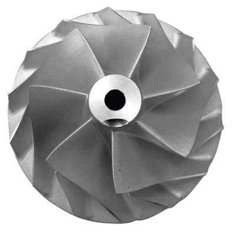
Figure 1: Cummins baseline conventional impeller
Inverse Design Approach Splitter Treatment
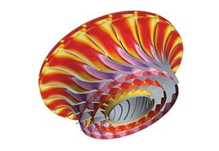
Figure 2 shows the type of loading that was used which is generally helpful in case of strong shocks. Using an aft-loaded distribution on the shroud helps to reduce the loading on the inducer and as a result, there is a reduction in the shock strength. The redesigned impeller was obtained within a week, which was a three-dimensional impeller as opposed to the straight filament baseline design.
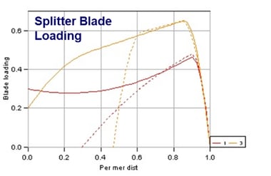
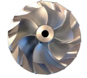
Figure 2: Optimum blade loading for shock control in transonic impellers (left) and resulting inverse designed impeller (right)
CFD Predictions at Design 95% Span
A comparison of the flow field between the two designs can be seen in Figure 3. While there is a strong shock in the inducer of the conventional baseline, its strength is reduced in the inverse designed geometry, and so is the complex interaction with the tip clearance vortex. The tip clearance vortex itself is weaker in the redesign, and therefore a combination of these two can be achieved through the specified blade loading.
Figure 3: Comparison of Mach number contours
The blade loading plot at 95% span shown in Figure 4 is also very useful because it clearly illustrates the reduction in the inducer shock strength, which was very strong in the conventional design.
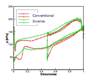
Figure 4: Comparison of static pressure distribution
Mechanical Analysis
Since the resulting impeller was three-dimensional, some detailed stress analysis was also performed. It was found that the maximum stress levels were quite similar between the conventional and the inverse impeller, just the location was different. While the original impeller showed peak stresses near the hub, the new impeller had them in the middle of the blade as shown in Figure 5. Therefore, there was no difference between these two impellers in terms of reliability.
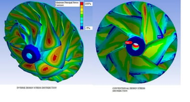
Figure 5: Comparison of stress distribution between inverse (left) and conventional (right) impellers
Figure 6 presents the improvements in efficiency between the inverse design and the baseline as measured in the test facility over the map. It can be observed that a 2.5% to 3% improvement in efficiency on this impeller was achieved over a large part of the map.
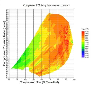
Figure 6: Compressor efficiency improvement contours
Book a LIVE demo on the design of a turbomachinery application of your choice.
Our demo is tailored to your specific application and design challenges

Share This Post