Across the specific speed range, compressors are subject to various flow phenomena and loss mechanisms which are dominant in that particular range. For example, leakage and secondary flow effects are more dominant in lower ranges, whereas profile/shock losses and corner separation in diffusers take priority in the higher ranges. In this article, we focus on shocks and how to come up with a set of optimal design guidelines to control this particular loss mechanism in a compressor.
Here we look at quite a well-known case, the SRV2 impeller that has been subject to very detailed LDV measurements at DLR in Germany. A redesign study was also performed as a collaboration between DLR, Mann Turbo and ABB Turbo, in which it was attempted to optimize the impeller by making changes to the meridional shape and blade angles. After testing 24 different geometries, even though the performance improved by about 2 points at 100% speed, but it was less than the baseline SRV2 impeller at 80% and 90% speeds. Now it will be discussed how the inverse design approach resulted in a higher performing impeller at both design as well as off design speeds.
CFD Validation
Since simulation accuracy is very important with these very high pressure ratio compressors, Figure 1 presents some CFD validation results. For this, the LDV measurements were used that were supplied by DLR to validate the CFD calculations. Although there is a small region missing near the endwalls because of reflections, a good match can be noticed between the simulation and the LDV measurements, both before and at the trailing edge plane. This provides confidence that the CFD results are sufficient to compare the performance of the redesign with the baseline.
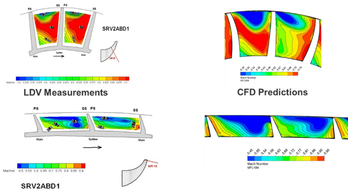
Figure 1: CFD validation results of SRV2 impeller
Specified Loading Distribution
Initially an aft-loaded distribution was used which is generally helpful in case of strong shocks, because this helps to reduce the loading on the inducer and as a result, there is a reduction in the shock strength. However, with these very high tip speed impellers, a certain throat area is required in order to have a wide choke margin and to match the choke margin of the baseline. So as the initial loading with zero leading edge incidence resulted in insufficient throat, the throat information from inverse design was used to adjust the leading edge loading until the throat area of SRV2 was matched, and then this was confirmed by CFD computations. Figure 2 shows the final distribution which is:
- Aft-loaded at the hub with a very high incidence at the hub and mid-span
- Generally aft-loaded at the shroud with high leading edge incidence
And this then showed that the right level of choke margin was obtained.
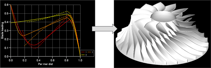 Figure 2: Optimum blade loading for shock control in SRV2 impeller (left) and resulting inverse designed impeller (right)
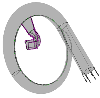
A comparison of the three-dimensional geometries is presented in Figure 3, which shows that the baseline SRV2 impeller is a straight filament design as opposed to the three-dimensional inverse designed impeller.
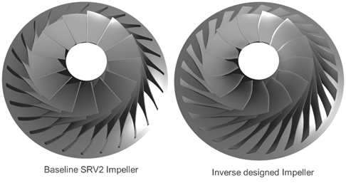 Figure 3: Baseline SRV2 (left) and inverse designed impeller (right)
Structural and Modal Analysis
At such high pressure ratios, it is very important to look at the mechanical aspects of the design as well, and so FEA analysis comparisons were performed between the baseline and the inverse design. Figure 4 shows the results of the Von Mises equivalent stress on the main blade pressure and suction surfaces, and it was found that the maximum level of stress was similar to the baseline SRV2 impeller and only the distribution was different.
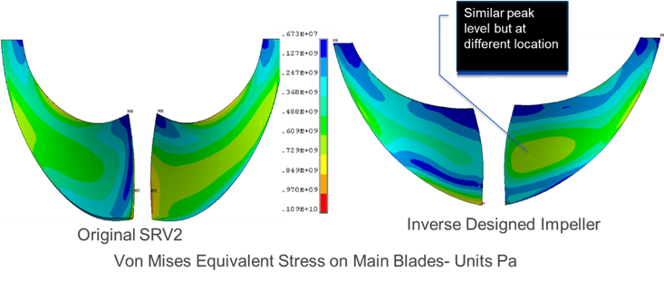
Figure 4: Von Mises equivalent stress on main blade
Figure 5 shows similar result on the splitter blade. Here, even though the maximum stress on the splitter is higher than on the original, the level of this maximum stress is much lower than the maximum allowable stress and so the design is well within the safe margin. Modal analysis results are also shown which confirm that there are significant improvements in the first, second, third and fourth modes. Therefore, there are significant advantages in terms of vibration response of this three-dimensional impeller.

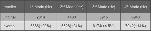
Figure 5: Von Mises equivalent stress on splitter blade
Performance Comparison
A comparison of the CFD predictions between the baseline SRV2 and the inverse design can be seen in Figure 6. It can be observed that in terms of efficiency, there is a gain of between 2.5 to 3 points across the whole operating range. So the improvement was not only at 100% speed, but also at part-load conditions which is very important if, for example, this was a turbocharger compressor for a diesel or marine application.
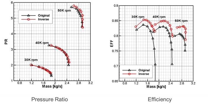
Figure 6: Performance comparison between baseline SRV2 and inverse design
Spanwise Mach Numbers – 100% speed
In Figure 7, the detailed flow field shows a strong normal shock at 50% span of the conventional design, which is reduced to more of a bow shock with reduced Mach number levels in the inverse design. Additionally, at 90% span, a reduction in shock strength and in the low momentum fluid that seems to have accumulated in the blade passage can also be noticed.
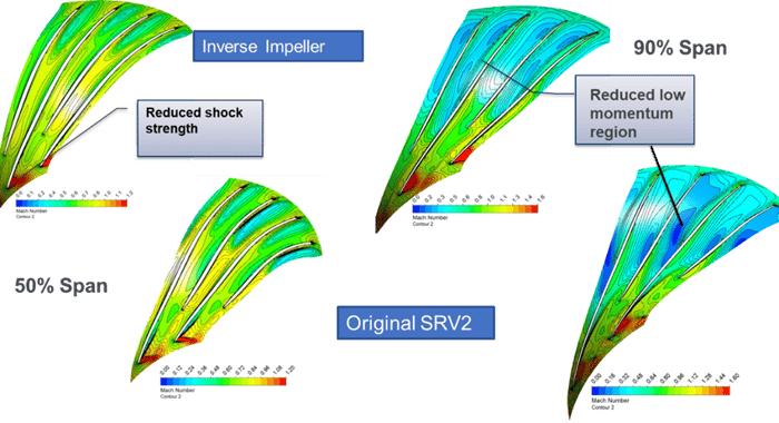 Figure 7: Mach number comparison at 50% and 90% span
Exit Flow Distribution – Relative Velocity
Looking at the exit flow from the impeller in Figure 8, a significant improvement in the exit flow non-uniformity can be seen in the inverse impeller. Therefore, the reduction in shock strength and the more uniform exit flow are the two main reasons for improvement in the impeller efficiency.
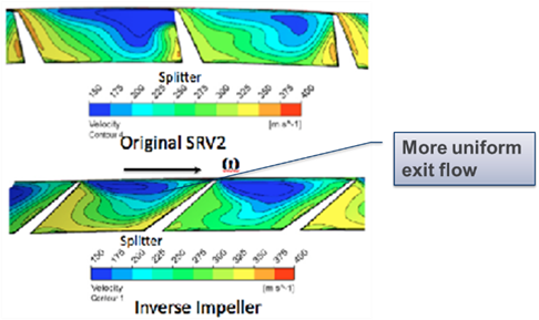
Figure 8: Relative velocity comparison at impeller exit
Book a LIVE demo on the design of a turbomachinery application of your choice.
Our demo is tailored to your specific application and design challenges

Share This Post