In this article, we look at the design and optimization of pump blades using a 3D Inverse Design method. We also discuss the overall design strategy, CFD analysis, and further optimization.
The tremendous development of numerical methods and computer technology has made Computational Fluid Dynamic technique (CFD) one of the most essential tools for the hydrodynamic design of pumps. A pump designer can evaluate the design numerically by CFD in advance of experimental model tests and obtain a significant amount of information on 3D flow fields, which helps improve the design. Along with the development of 2D and 3D CAD systems, a variety of blade/passage design systems have been proposed and combined with a CFD system, which accelerates the design and redesign process for pump blade design optimization.
-
Case Study 1: Suppressing Secondary Flows in Impeller Design
-
Case Study 2: Diffuser Optimization to Suppress Corner Stall
-
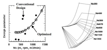
Achieving Challenging Designs: Compactness and High Suction Performance
Why Traditional Pump Blade Design Optimization Fails
However, the fundamental problem for such approaches is the way to define the blade/passage shape, such as the blade angle distribution between the leading and the trailing edge. This relies significantly on empiricism and the experience/intuition of an expert designer. The designer tries to improve the design by changing the blade/passage configuration based on the information obtained by CFD.
The partial modification of the blade/passage configuration affects the entire flow field, and a trial-and-error redesign process can be very inefficient. Conventional design approaches like this face difficulty in improving pump performance, which is often already at a high level, or in optimizing pump configuration for a critical design specification beyond previous experience. In addition to this, the demands of supplying a custom pump at low cost and quick delivery time are increasing, and the design cycle and pump design strategy need to be more efficient.
The 3D Inverse Design Methodology and Workflow
The design system consists of a blade design system, a 3D CAD modelling system, and a rapid prototyping (RP) manufacturing system. Following the design specification, the blade design starts with a meridional configuration of impellers/diffusers. Then the blades are designed subject to a specified circulation distribution using the 3D Inverse Design method.
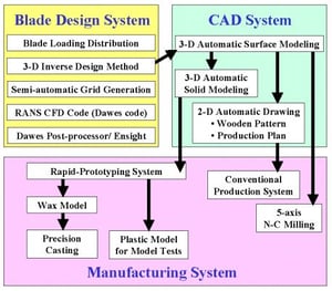
The CFD's computational grids are generated semi-automatic, employing H-type grids. Next, the 3D flow fields within the impellers/diffusers are analyzed and evaluated by solving the equations. For diffuser blades, a code is used. In the design evaluation process, the commercial visualization software with macro commands was prepared to visualize 3D flow fields efficiently in daily design work. The use of this system is suitable for the systematic design of impeller/diffuser blades with different meridional shapes and blade loading distributions, which enables a high-speed optimization of the design parameters.
The 3D CAD system starts from the 3D surface model of the impeller/diffuser blades, which is done automatically by a macro command of the 3D CAD system. The 3D blade configuration, generated by the inverse design system, is directly fed into the solid modelling process using a 3D CAD system and then manufactured by Rapid Prototyping (RP) using Laser Stereo Lithography (LSL) or Selective Laser Sintering (SLS).
How 3D Inverse Design Optimizes Pump Blade Geometry
Using the 3D Inverse Design method, the blades are represented by sheets of vorticity and the strength is determined by a specified distribution of bound circulation 2π θ rV. Here, Vθ is a circumferential averaged swirl velocity. The CPU time required to obtain a converged blade shape is very short - typically a few minutes on a modern PC. The significant advantage of using the Inverse Design method is complex 3D geometry of the blade with controlled 3D pressure fields can be designed very rapidly based on a simple distribution of bound circulation.
The inverse method can be applied to impellers, diffusers, stay vanes etc. The basic design process for a diffuser is identical to that of an impeller blade except that the effects of a non-uniform outflow from the upstream impeller should be considered. To extend the method, you can include the effects of inlet shear flow, which is important for the design of a blade row receiving a non-uniform inflow. The outflow from the impeller is predicted by CFD and thus obtained non-uniform velocity distribution is used as the inlet boundary condition for the inverse design of the diffuser blades.
The inputs of this design method are as follows:
- Meridional passage configuration
- Loading distribution (distribution of bound circulation 2π θ rV)
- Rotational speed ω, which is zero for a stationary blade
- Blade thickness distribution
- Blade number
- Stacking condition
Among these, the meridional passage configuration and the loading distribution are the most important design parameters. The design inputs based on existing knowledge usually give a reasonable starting point for optimizing blade shape. Still, each design input parameter may be optimized further through a systematic application of Inverse Design and CFD evaluation while keeping other design parameters the same.
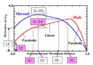
In the design system on the left, the blade loading is specified by giving the distribution, which is the derivative of angular momentum rVθ along the meridional distance. The figure below shows the schematic distribution of the blade loading parameter for an impeller.

Validating Inverse Design: The Role of Viscous CFD Analysis
The Inverse Design method assumes a potential flow. So the important viscous flow features, such as secondary flows and flow separation, must be evaluated by the application of CFD codes. The Inverse Design method has become a very practical and powerful tool because of the recent significant advancement of a 3D viscous CFD code.
The following items are evaluated based on the CFD prediction of impeller/stage flows.
- Euler head (work input)
- Impeller and stage efficiency
- Suction performance (minimum pressure in impeller)
- Impeller stall characteristics (onset of inlet recirculation)
- Diffuser stall characteristics (onset of corner flow separation)
- Velocity distortion at impeller/diffuser outlet 5
- Secondary flows and other internal flow fields
Here, the stage efficiency is calculated including the mixing losses downstream from the stage exit due to exit swirl and flow non-uniformity.
Explore the underlying physics of blade loading in the following articles:
1. What is blade loading and how is it specified?
2. Blade Loading, Inverse Design and Shape Parameterization
Case Study 1: Suppressing Secondary Flows in Impeller Design
Secondary flows in a centrifugal impeller are well acknowledged to drive the high loss fluids in the viscous layer toward the shroud/suction surface corner region. The secondary flow phenomena have important effects on the efficiency and stability of the impeller. In addition to this, the secondary flow has a dominating influence on the generation of the exit flow non-uniformity (so-called “jet-wake” flow pattern) and affects the performance and stability of the downstream diffuser. The meridional secondary flows on the blade suction surface are important since the boundary layers are thicker on the suction surfaces than on the pressure surfaces at around the design point.
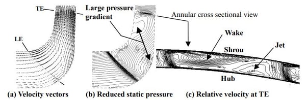
Figure (a) shows the flow pattern near the suction surface of a conventional impeller having a typical blade angle distribution which connects the inlet and exit blade angles by smooth monotonous curves. The specific speed of the impeller is 280 [m, rpm, m3 /min]. The strong spanwise secondary flow was generated by the large gradient of reduced static pressure between the hub and the shroud, see Figure (b). Here, reduced static pressure is the pressure on rotational frame of reference and defined by p – 0.5ρ(rω) 2 . Because of the strong secondary flows, the exit flow non-uniformity became very high and well-known jet-wake flow pattern was established as shown in Figure (c).
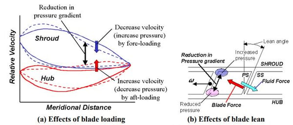
The secondary flow control by the 3D inverse design method is straightforward as we can easily control the pressure fields by controlling the blade loading parameter. The effect of blade lean can be used to control the pressure gradient in the spanwise direction. The spanwise component of the blade forces created by the blade lean increases the average pressure on the shroud side while reducing the pressure at the hub side. The blade lean can be specified at one meridional location as an initial condition to obtain blade shape by the inverse design method. The figure below shows the flow field in conventional impeller at design point.
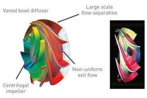
Case Study 2: Diffuser Optimization to Suppress Corner Stall
The hub surface of a vaned bowl diffuser, having a shorter blade length compared to the shroud side, can be highly loaded when the outer diameter of the diffuser is made compact. Under such a situation, the optimization of blade shape is extremely important to avoid a large-scale flow separation along the corner region between the diffuser blade suction surface and the hub surface.
The figure shows the results of CFD prediction for a conventional diffuser pump stage with low specific speed (280 [m, rpm, m3 /min]), which presents 3D representation of the wall surface streamlines, static pressure contours and the velocity contours at the diffuser TE plane.
The figure shows the velocity vectors, the static pressure contours on the blade suction surface, and the total pressure contours on an annular cross-section at 59%-chord location of the conventional diffuser. The spanwise pressure gradient on the diffuser blade suction surface, the spanwise secondary flows were generated towards the hub surface. There was more than 5 points in improvement in peak efficiency, matching at design flow rate and 1/3 of the loss reduction was from re-designed impeller.
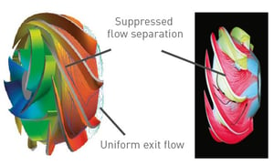
The overall pump performance is measured experimentally by model tests. All data were normalized by the value at the best efficiency point of the conventional design. Significant improvements were obtained in the inverse design for the whole flow range below 125% of the design flow rate. The peak efficiency was improved by more than 5 points. The impeller was 7 also redesigned by the 3D inverse design method, and CFD prediction showed one-third of the loss reduction is attributed to the loss reduction in the impeller. According to the CFD prediction, the pressure recovery coefficient of the inverse design diffuser was 0.77, while it was 0.58 for the conventional diffuser.
Achieving Challenging Designs: Compactness and High Suction Performance
The 3D pressure field is controlled precisely using the 3D inverse design method, which enables challenging design beyond our previous experiences such as super compact design and high suction performance design.
A typical design process of a pump stage starts with the selection of initial meridional configuration, blade number, and blade thickness distribution. Previous experience will give a reasonable starting point for most cases. Firstly, the blade loading parameter is optimized for the specified overall swirl (or Euler's head) distribution in the spanwise direction. Then, the meridional configuration is optimized while keeping the same hydrodynamic design parameters for the inverse design. Finally, the blade loading parameter is tuned again to maximize, for example, the efficiency predicted by CFD.
The optimization process is the same between the impellers and diffusers, but the meridional configuration of the impeller must be arranged considering the downstream diffuser arrangement. Especially for super compact designs, the blade loading parameters must be carefully controlled to suppress major flow separation and to avoid low pressure in the flow passage.
Systematic Pump Design Strategy Using 3D Inverse Design
In the 3D Inverse Design method, it is very easy to apply the above-mentioned design strategy to other similar designs and to construct more systematic and universal design know-how. This is because the principal design parameter (blade loading) is a hydrodynamic parameter having a universal nature.
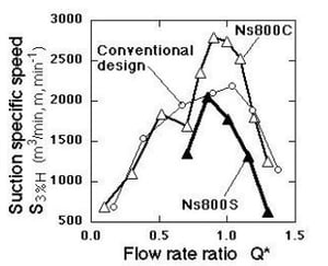
It should also be emphasized that a design procedure based on a 3D inverse design is essential for optimizing the blade shape further beyond our current state-of-the-art design. This is true even for axial flow pumps since the spanwise blade force has large effects on the 3D pressure fields. Using the present design system, the diffuser pump series with a compact machine size was designed to achieve high efficiency and high suction performance beyond conventional pump design.
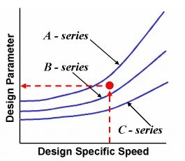
Each of the design parameters, which 9 specify the optimum blade loading distribution and the optimum meridional shape, was described by an analytical equation, which was defined as a continuous function of a pump-specific speed. So, the optimized design of a pump at an intermediate specific speed is very straightforward, and a good overall performance is always assured.
The key aspect of this new design strategy is the efficient and systematic optimization of the principal design parameters. In the present design system, it is typically possible to evaluate twenty design cases per day, which can drastically change the design work. However, it should be noted here that the existing good designs by the conventional method would give a good starting point for the further optimization process by this new design strategy.
During the inverse design optimization process, we should always think about the hydrodynamic meaning of the existing design practice that gives good results. It is helpful to focus on the design know-how of our predecessors since we can integrate it into the present new design system more logically, which in turn reduces development costs and accelerates further improvements of the pump design.
Would you like to discuss your current pump design software and design strategy?
Get in touch now and learn how to optimize your blade loading and pump design process.
Book a LIVE demo on the design of a turbomachinery application of your choice.
Our demo is tailored to your specific application and design challenges


Share This Post