Across the specific speed range, compressors are subject to various flow phenomena and loss mechanisms which are dominant in that particular range. For example, leakage and secondary flow effects are more dominant in lower ranges, whereas profile/shock losses and corner separation in diffusers take priority in the higher ranges. In this article, we focus on secondary flow effects in impellers with splitter blades and how to come up with a set of optimal design guidelines to suppress this particular loss mechanism in a compressor.
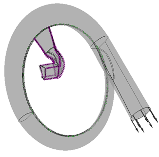
The case in question is a subsonic impeller with splitter blades, and this was a collaboration between ADT, ETH Zurich, Sulzer Turbo and ABB Turbo. The experimental setup and the corresponding specs are given in Figure 1.
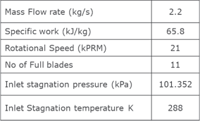
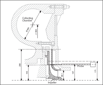
Figure 1: Cross-sectional view of the compressor at ETH Zurich
Secondary Flows in Impellers
Generally, the dominant source of loss in subsonic impellers is secondary flows. Thus, the specified loading type should be aimed at controlling these secondary flows. Figure 2 shows the actual flow field that was predicted for a conventionally designed impeller:
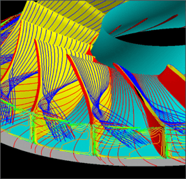
Figure 2: Secondary flows in a conventional subsonic impeller
The streamlines, that were created very close to the blade suction surface, reveal strong secondary flows moving the low momentum fluid that is generated on the suction surface from the hub towards the shroud trailing edge region. It can also be seen that these low momentum fluids in the boundary layer are being moved by the secondary flows and result in the formation of exit flow non-uniformity at the exit of the impeller, which can result in:
- high mixing losses
- high diffuser and stage losses
- compressor instability at least in the case of vaned diffusers
As this is one of the major sources of loss for many industrial applications at least for subsonic impellers, the optimum blade loading should be aimed at reducing this exit flow non-uniformity.
Secondary Flow Theory
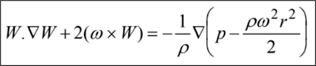
From Classical Secondary Flow theory (Zangeneh et al, 1988) it can be shown that:
![]()
Here W is the velocity, Ω is the absolute vorticity, and so (W.Ω) is the streamwise vorticity. Therefore, this shows that streamwise vorticity will be generated along a streamline if there is a component of vorticity in the direction of streamline curvature acceleration or a component of vorticity in the direction of Coriolis acceleration. Based on this, the rotating channel can be divided into these three parts:
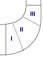
Figure 3: Rotating channel sections
Generally, there are negligible secondary flows in the inducer region since the boundary layer has not grown very much. Also, the radial section mainly sees the tangential component of Coriolis acceleration. However, when it comes to section 2 (axial to radial bend), there are multiple contributions resulting in secondary flows on the hub from the pressure surface to the suction surface. These then finally get moved up along the suction surface and are then dumped near the trailing edge. So, what the above equation shows is that in section 2, there are very complex secondary flow patterns moving low momentum fluids both at the endwalls and the blade surfaces, and then moving all these losses to the tip trailing edge plane.
In fact, the momentum equation can be used to express the Coriolis and streamline curvature accelerations in terms of gradients of reduced static pressure as follows:
This is for incompressible flow, whereas for compressible flow this will be enthalpy. It can be shown then that secondary flows are generated whenever there is a gradient of reduced static pressure (or relative Mach number in the case of compressible flows) in the direction of vorticity in the flow field. Eventually, this becomes a very easy way of looking at the problem and solving the issue.
Blade Surface Mach Number
If the relative Mach number on the conventional impeller blade is plotted as in Figure 4, it can be observed that the secondary flows are driven by the difference between the suction surface of the shroud and the suction surface of the hub. Therefore, if this gap can be reduced, then it should be possible to suppress the secondary flows. In the inverse design method, it is possible to directly control the pressure jump across the blade or the blade loading and therefore, by making appropriate changes to the blade loading, we could very easily adjust the overall surface Mach number in such a way that we reduce the gap, as we show in this example. And this should then help to reduce secondary flows in the impeller.

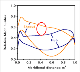
Figure 4: Surface Mach number distribution on conventional (left) and inverse (right) impeller
Optimum Loading for Secondary Flow Control
A significant advantage of using inverse design is that the individual loading on the splitter and the full blade can be adjusted independently, and then the program automatically finds the optimum pitchwise location of the splitter. Figure 5 shows the prescribed loading distribution which is fore-loaded at the shroud and aft-loaded at the hub, and it may be noted that this is the same for both the full blades (black lines) as well as the splitters (red lines). The net effect of this type of change is that essentially, it helps raise the suction surface hub velocity and reduce the suction surface shroud velocity, and therefore reduces the gap mentioned earlier.
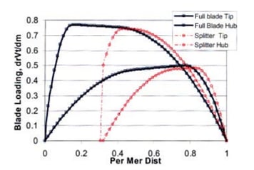
Figure 5: Optimum blade loading for secondary flow control in full blades and splitters
Computed Geometry
Figure 6 shows the resulting impeller using the optimum loading along with a comparison of the blade angles. As expected, the blade angles are the same between the full blade and the splitter for conventional design. However, for the inverse design, there is approximately a 5-degree difference between the splitter and the full blade. The difference is much smaller at the hub, both between the splitter and the full blade, and even between the conventional and inverse designs. This is probably because the conventional impeller was aft-loaded both at the hub and shroud, while the redesign is fore-loaded at the shroud and aft-loaded at the hub.
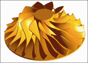
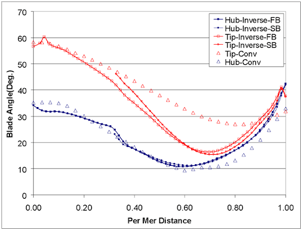
Figure 6: Inverse designed impeller (top) and blade angle comparison with conventional design (bottom)
Comparison of Measured Results
Using the ability to do fast-response probe measurements, Figure 7 shows the relative velocity at the exit of the conventional (lower) and inverse (upper) impellers. Quite significant non-uniformities are visible in the conventional impeller, especially in the channel between the splitter suction surface and the full blade pressure surface, and there is strong variation both in spanwise as well as pitchwise directions. However, the inverse impeller shows much lower pitchwise and spanwise variation as a result of better control of secondary flows.
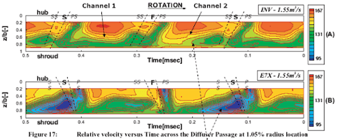
Figure 7: Measured relative velocity at impeller exit of inverse (upper) and conventional (lower) designs
The total pressure measurement data is shown in Figure 8, and once again a region of accumulation of low momentum fluid around the suction surface can be observed in the conventional impeller, whereas it is eliminated from the inverse impeller.
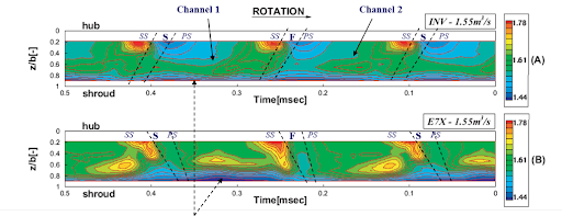
Figure 8: Measured total pressure at impeller exit of inverse (upper) and conventional (lower) designs
Measured Performance
The probe measurements also made it possible to measure the efficiency at the exit of the impeller which are shown in red in Figure 9, and there was about 2 points improvement in efficiency at the impeller exit. For the mixed-out conditions at the stage exit, there was actually a 5 to 6 points improvement, which confirms that by making the impeller flow more uniform, it is possible to get quite substantial improvements in efficiency as a result of reduction in mixing losses at the impeller exit.
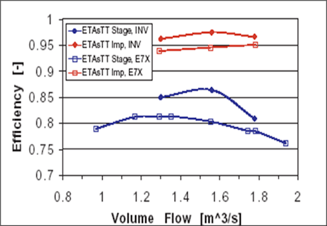
Figure 9: Measured impeller and stage efficiency comparison
Book a LIVE demo on the design of a turbomachinery application of your choice.
Our demo is tailored to your specific application and design challenges

Share This Post