One of the most important issues in design of centrifugal compressors is to understand what is the main source loss in the impeller and how changes to impeller geometry or blade loading can impact these sources of loss.
In order to establish these important sources of loss a method based on entropy production rate was developed in a paper presented at ASME IGTI 2021, see [1].

The various losses generated from different flow mechanisms (such as skin friction, secondary flow, tip clearance vortex and shock waves) can be quantified from the computational fluid dynamics simulations.
The breakdown of losses is achieved by separating the flow field into different zones. Each zone is defined by the flow physics rather than by geometrical locations or empirical correlations, which makes the method a more general approach and applicable to different machine types. The method has been demonstrated on both a subsonic and a transonic centrifugal compressor.
With a good understanding of loss mechanisms inside an impeller, it is possible to carry out optimisations using the inverse design method (TURBOdesign1), with the target of reducing certain losses through blade loading control. TURBOdesign1 already provides feedback on profile loss, secondary flow loss and leakage losses by correlating these losses with isentropic Mach number or velocities.
Loss Decomposition
The loss decomposition for the optimized design is also generated to assess the impact of design optimisation. To decompose the flow field the following criteria are used:
• The shock zone is identified from the flow field using the density gradient on the normalized velocity vector.
• The boundary layer zone is identified by the high turbulence eddy dissipation.
• The secondary flow zone is identified by using vortex identification.
• The tip clearance flow is further separated from the secondary flow vortex by the turbulence kinetic energy and by the absolute helicity.
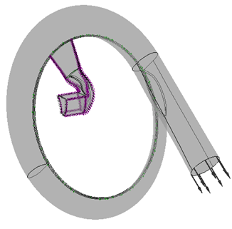
The Eckardt’s impeller ‘A’ is studied in the paper and used as a benchmark example. The flow field decomposition is shown in Figure 1.
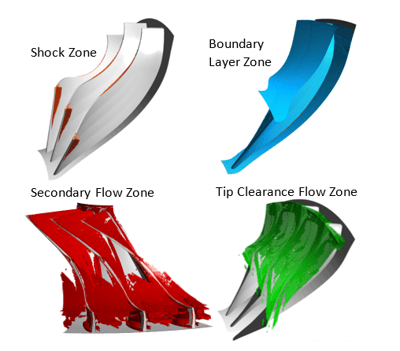
Fig. 1. Flow field decompsition for Eckardt impeller A.
Once the loss breakdown is obtained, a multiobjective direct optimisation is carried out within TURBOdesign Suite using the inverse design solver TURBOdesign1 and a genetic optimizer (TURBOdesign Optima). The inverse design solver
converges on a single core within a few seconds, so it can be coupled to an optimizer to explore the design space quickly. Since the boundary layer friction and secondary flow produce the major portion of total loss, the optimisation objectives are set to minimize the profile loss and the secondary flow factor. These two parameters can be deduced from the inverse design solution and no CFD simulations are needed during the optimisation. The final optimized design is shown in Figure 2, in comparison to the original Eckardt impeller A.
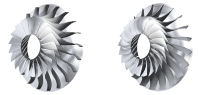
Fig. 2. Eckardt impeller A and ‘inverse design optimized’ impeller.
The loss breakdown shows by suppressing the passage secondary flow and limiting the blade profile loss the overall impeller passage loss is reduced (Figure 3). As a result, the impeller efficiency is improved with the pressure ratio maintained.
%20at%205.31kgs%20for%20the%20Eckardt%20impeller%20A%20and%20the%20optimized%20design%20(14k%20rpm)..png?width=361&name=Figure%203%2c%20Entropy%20generation%20rate%20(decomposed%20by%20sources)%20at%205.31kgs%20for%20the%20Eckardt%20impeller%20A%20and%20the%20optimized%20design%20(14k%20rpm)..png)
Fig. 3. Entropy generation rate (decomposed by sources) at 5.31kg/s for the Eckardt impeller A and the optimized design (14k rpm).
The contour plot of velocity variant Q at the trailing edge of the impeller (Figure 4) shows the high vorticity area is greatly reduced for the optimized design. The reduction of vortices in the passage (especially near the shroud) results in less loss created by secondary flow and the tip leakage vortex. The improvement on the impeller existing flow also reduces the loss in the downstream vaneless diffuser. At the vaneless diffuser outlet, the peak efficiency of the optimized design is about 1.6% higher than the Eckardt impeller A.
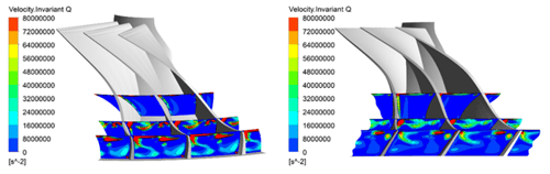
Fig. 4. Contour of velocity invariant Q for the baseline and the optimized design.
A Detailed Loss Analysis Methodology for Centrifugal Compressors
We invite you to playback this webinar to discover the whole process for centrifugal compressors where you will:
- Learn how to apply entropy production to understand the sources of loss in any turbomachine;
- Discover the main sources of loss in centrifugal compressors and their relative importance under different operating conditions;
- Validate how the different loss mechanism change in a subsonic and transonic compressor.

References
1. Luying Zhang, Loukia Kritioti, Peng Wang, Jiangnan Zhang, Mehrdad Zangeneh, 2021, “A Detailed Loss Analysis Methodology for Centrifugal Compressors,” Proceedings of ASME Turbo Expo 2021: Turbomachinery Technical Conference and Exposition, June 7-11, 2021, Virtual, Online. This will be published in ASME Journal of turbomachinery.
Book a LIVE demo on the design of a turbomachinery application of your choice.
Our demo is tailored to your specific application and design challenges

Share This Post