The first part of this article showed how to make use of the different options in TURBOdesign1 to rapidly generate three different turbopump configurations:
- Separate inducer with secondary impeller
- Separate tandem inducer with secondary impeller
- Single piece inducer and impeller (splitter)
In this second part, we first demonstrate how TURBOdesign1 can be used to perform a rapid DOE study on tandem inducers to determine the best meridional and work split for their optimum cavitation behaviour. Then a performance comparison based on CFD analysis of the different turbopump configurations will also be presented.
Tandem Inducer Design
In the past, tandem-bladed inducers have produced higher head compared to typical flat-plate inducers, such as the one described in a NASA technical note [1]. They also tested different clocking options and saw that the maximum head rise was achieved when the exducer blade was clocked in the direction of rotation. Now in the first part of the article, it was already shown that tandem inducers can be quickly generated in TURBOdesign1 by taking the original inducer, and then specifying a particular loading and meridional split between the inducer and exducer blades as shown in Figure 1. In addition, since blade surface minimum pressure is one of the performance parameters we get from the inverse design solver, this can naturally be used to perform a fast DOE to determine the best meridional and loading split between the inducer and exducer blades for optimum cavitation behaviour.
Figure 1: Tandem inducer clocking [1], work and meridional parametrization
Tandem Inducer DOE
Regarding the DOE procedure, the different tandem designs are generated by gradually increasing the inducer meridional length and correspondingly reducing the exducer meridional length, and then by gradually increasing the inducer work and correspondingly reducing the exducer work. For each tandem design, the global minimum pressure is noted on the inducer and exducer blades combined, and then a table of global minimum pressures for all the tandem designs is created as shown in Figure 2. From this, it is quite straightforward to pick the design with the highest minimum pressure, which is 70% meridional length and 60% loading on the inducer in this case. The static pressure plots from TURBOdesign1 clearly show that the minimum pressure is greater than the vapour pressure, removing the possibility of cavitation in this design, and so this is used as the final design for the tandem turbopump configuration. In contrast, it can also be observed that a 50/50 split for the meridional length and loading is not necessarily the best option, since the minimum pressure goes below the vapour pressure in this case.
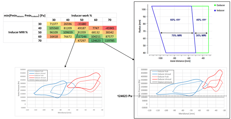
Figure 2: Tandem inducer DOE study for cavitation optimization
CFD Setup
Once the three turbopump configurations are ready, CFD runs are performed to check their actual performances. As Figure 3 shows, ANSYS TurboGrid is used for the fully structured grids of the inducer and the impeller, and CFX for the flow analysis. Below are the various CFD settings where the boundary conditions are chosen to match the inlet and outlet conditions in the TURBOdesign Pre case:
- P01 = 206843 Pa
- m2 = 70.31 kg/s
- Rotor-stator interface = frozen rotor
- Turbulence model = k-omega SST
- Total mesh size ≈ 1.2 – 2.6 M
- Average blade y+ ≈ 3 – 4
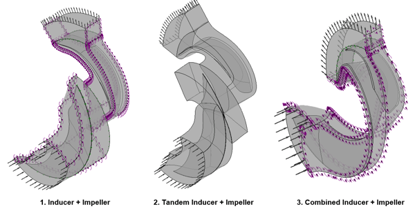
Figure 3: CFD setup of turbopump configurations
From this information we can use design tools and 3D CFD to investigate our turbopump designs, and what follows is a set of principal design guidelines based on the fluid dynamics considerations of reducing dominant flow losses for a given inducer/impeller.
CFD Results
Figure 4 confirms that when CFD analysis is performed on the three turbopump configurations, all of them are able to achieve the target head of 2681 m from the TURBOdesign Pre report, indicating that all of them should be able to achieve the stage head of 2575 m when combined with the volute. Importantly, the head generated by the tandem inducer is considerably higher than the flat-plate inducer, confirming the benefits of the tandem-blade approach. Another interesting result is that the CFD efficiencies show a very good correspondence with the meanline code prediction, and that the work coefficient or rVt* that was specified in TD1 is quite close to what is actually obtained from CFD at the different stations for all the three turbopump configurations.
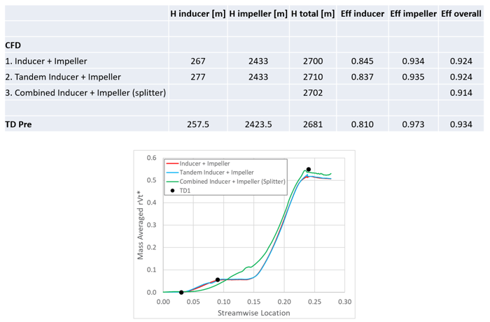
Figure 4: Turbopump stage specifications
Figure 5 presents the blade loading plots from CFD, and it can be clearly seen that all three turbopump designs are able to stay above the vapour pressure line of liquid hydrogen, something that was already predicted by the TURBOdesign1 performance parameters. This verifies that the tandem inducer that was selected from the DOE study produces a higher head but without creating any risk of cavitation.
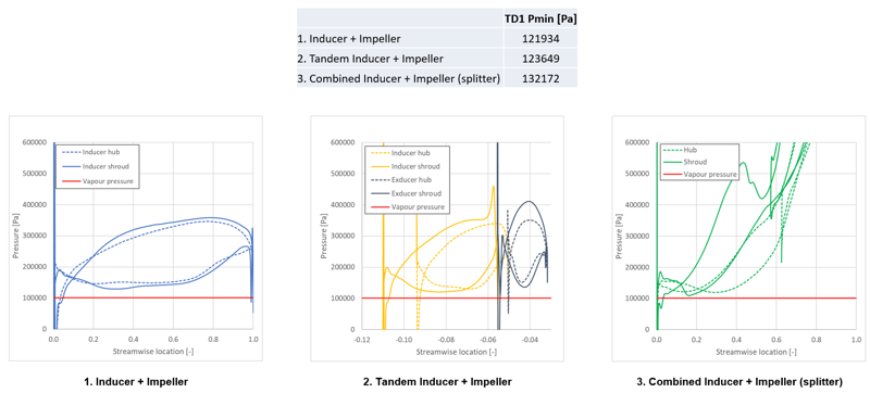
Figure 5: Meanline design of turbopump stage in TURBOdesign Pre
Finally, the velocity vector plots in the blade-to-blade views of Figure 6 confirm good flow behaviour throughout the impeller and the inducer in all the three configurations. Additionally, a zoom of the tandem inducer clearly reveals the flow energization through the inducer/exducer gap.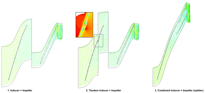
Figure 6: 3D blade design of a separate inducer followed by an impeller in TURBOdesign1
Conclusion
Since tandem inducers can be easily generated in TURBOdesign1 with specific loading and meridional splits, it can naturally lead to a rapid DOE for an optimum design. As confirmed through CFD analysis, all the three turbopump configurations designed in this work are able to exceed the required head and avoid the scenario of cavitation. Furthermore, the tandem inducer is seen to generate a higher head compared to the flat-plate inducer without compromising on the cavitation aspect.
References
[1] Soltis R. F., Urusek D. C., Miller M. J., “Blade-element Performance of a Tandem-bladed Inducer Tested in Water”, NASA Technical Note NASA TN D-5562

Book a LIVE demo on the design of a turbomachinery application of your choice.
Our demo is tailored to your specific application and design challenges


Share This Post