Turbopumps are mainly used in rocket engines and in low suction pressure situations in the industry. As Figure 1 shows, their suction specific speed is very sensitive to the inlet eye diameter and the leading edge blade angle [1], and this makes a cavitation-free performance difficult to achieve using traditional methods.
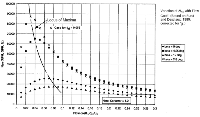
Figure 1: Suction specific speed as a function of inlet blade angle and impeller flow coefficient [1]
However, the 3D inverse design method makes it possible to quickly design various turbopump configurations under industrial timescales and with a good cavitation performance. In this work, we will look at three such configurations. In the first configuration, the inducer is mounted separately on the pump shaft upstream of the impeller. The second one is similar but the inducer is split into a tandem inducer and tandem exducer components. Finally, the third one is a splitter type configuration where the inducer is an integral part of the impeller.
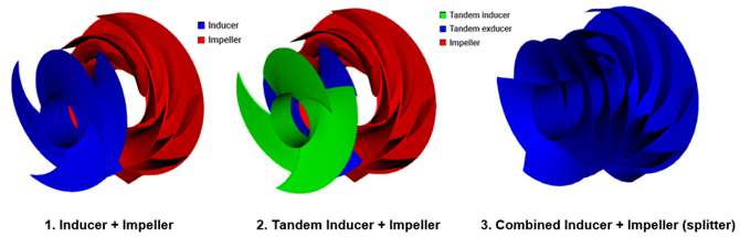
Figure 2: Turbopump configurations using 3D inverse design
Turbopump Design Process
The first step in the design of any turbopump is to identify the required specific speed regime. This will dictate the meridional shape and hence the general flow direction through the turbopump. For example, a low specific speed turbopump is likely to be a radial or centrifugal type, whereas a high specific speed turbopump is likely to be of mixed flow or axial type.
From the required specific speed, we can identify the main flow phenomena and loss mechanisms dominant in that particular range as shown in Figure 2. For example, leakage and secondary flow effects are more dominant in lower ranges, whereas profile losses and corner separation in diffusers take priority in the higher ranges. On the other hand, a phenomenon such as cavitation can affect turbopumps over the entire specific speed range and must be dealt with on a case basis.
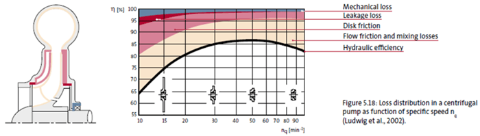
Figure 3: Loss breakdown in centrifugal pumps
From this information we can use design tools and 3D CFD to investigate our turbopump designs, and what follows is a set of principal design guidelines based on the fluid dynamics considerations of reducing dominant flow losses for a given inducer/impeller.
Meanline Design of Turbopump Stage
Figure 4 contains the specifications for the low-pressure hydrogen turbopump stage consisting of an inducer, impeller and a volute, which is based on the RS 25 space shuttle main engine.
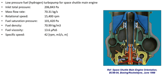
Figure 4: Turbopump stage specifications
Using the meanline code TURBOdesign Pre, it is very easy to enter the given specs and verify that it sits in the high efficiency region of the specific speed diagram and then it quickly generates the meridional shape of the turbopump stage in less than a second. As Figure 5 shows, it also provides a detailed report including the estimated stage performance and some important dimensions, as well as the required rVt* for the inducer and the impeller. This rVt* value is equivalent to the work coefficient and will be used for the 3D inverse design of these components in the next section. Furthermore, some performance maps (eg. stage head vs flow rate) are predicted and it is also possible to have an evaluation of the shaft power at various rotational speeds.
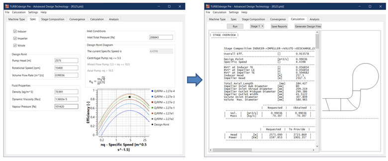
Figure 5: Meanline design of turbopump stage in TURBOdesign Pre
Turbopump Configuration 1: Inducer + Impeller
The 3D blade design of the three turbopump configurations is performed using our inverse design solver TURBOdesign1. Figure 6 presents the setup for the first configuration with a separate inducer followed by an impeller, where the meridional designs and loading settings automatically come from the meanline code TURBOdesign Pre. Furthermore, any thickness profile can be imposed to mitigate high stresses. The spanwise work distribution for each component is free vortex, and so it has zero swirl at the inlet, and a constant value from hub to shroud at the outlet. Importantly, the rVt* at the impeller leading edge is kept the same as the inducer trailing edge and this automatically ensures a good matching between them. The default loading distribution is aft loaded for the inducer and for this baseline impeller, it is fore loaded at the shroud and aft loaded at the hub, and then these inputs result in 3D geometries of the two components as shown alongside.
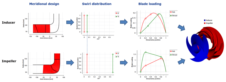
Figure 6: 3D blade design of a separate inducer followed by an impeller in TURBOdesign1
Software Demo - Configuration 1: Design of Turbopump Inducer and Impeller with 3D Inverse Design
Turbopump Configuration 2: Tandem Inducer + Impeller
Moving on to the second configuration in Figure 7, the impeller is generated in the same way as for the first configuration, but here the inducer is split into a tandem inducer and exducer blades. This can be done very easily in TURBOdesign1 by first generating the exducer blade, imposing the leading edge wrap angle on the inducer trailing edge, and finally using this to generate the inducer blade. In fact, this methodology was successfully used in one of ADT’s recent technical papers that was presented at the 15th European Turbomachinery conference [2]. Of course, the rVt* matching is maintained between the three components, and then these inputs result in 3D geometries of the tandem configuration as shown alongside.
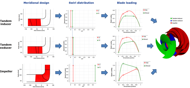
Figure 7: 3D blade design of a tandem inducer followed by an impeller in TURBOdesign1
Software Demo Configuration 2: Design of Turbopump Tandem Inducer with 3D Inverse Design
Turbopump Configuration 3: Combined Inducer + Impeller (Splitter)
Finally, for the third configuration presented in Figure 8, a splitter approach is adopted where the meridional shape is retained, and the splitter leading edge is placed at the same position as the impeller leading edge in the previous configurations. The work ratio between the full blade and splitter blades is specified in proportion to their relative meridional lengths for a balanced distribution, and the streamwise loading is aft loaded for both full and splitter blades. These inputs result in 3D geometry of the splitter configuration as shown alongside.
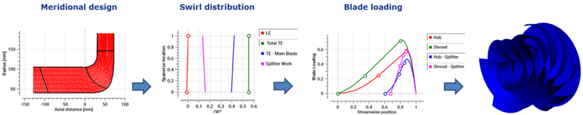
Figure 8: 3D blade design of a splitter-type combined inducer and impeller in TURBOdesign1
Software Demo Configuration 3: Design of Turbopump Splitter Impeller with 3D Inverse Design
Conclusion
While a high suction specific speed in turbopumps is difficult to achieve using conventional methods, the inverse design method makes it possible to quickly generate various turbopump configurations with a good cavitation performance. For example, tandem inducers can be easily generated in TURBOdesign1 with specific loading and meridional splits.
In the second part of this article, we demonstrate how TURBOdesign1 can be used to perform a rapid DOE study on tandem inducers to determine the best meridional and work split for their optimum cavitation behaviour. Also presented is a performance comparison based on CFD analysis of the different turbopump configurations.
References
[1] Furst, R., and Desclaux, J., “A Simple Procedure for Prediction of NPSH Required by Inducers,” Pumping Machinery 1989, ASME FED-81, ASME, New York.
[2] Oliveira, R., Zhang, L., Zangeneh, M., “Tandem-blade Centrifugal Compressor Design and Optimization by means of 3D Inverse Design”, Proceedings of 15th European Conference on Turbomachinery Fluid dynamics & Thermodynamics (ETC15), April 24-28 2023; Budapest, Hungary

Book a LIVE demo on the design of a turbomachinery application of your choice.
Our demo is tailored to your specific application and design challenges


Share This Post