In another article, based on one of ADT’s technical papers that was presented at the Turbomachinery Society of Japan [1], we cover the baseline design of an industrial compressor with return channel along with its CFD performance.
This article, based on the same paper, presents a complete multipoint optimisation methodology for the meridional geometry and the blade loading (blade shapes) of the baseline impeller, the vaned diffuser, crossover bend and the vaned return channel using 3D inverse design method, DOE (Design of Experiments), Kriging RSM (Response Surface Model) and MOGA.
Design Parameters
The optimization starts with a sensitivity study on the design parameters. For this, 10 meridional geometry parameters are selected first as described below and shown in Figure 1:
- W1: impeller inlet width
- α: impeller LE angle
- L2 : impeller axial length
- Xhub: controls the impeller hub curvature
- Yshr: controls the impeller shroud curvature
- W2: width of impeller tip, diffuser and crossover bend
- L3: diffuser length
- Rc: radius of crossover bend hub
- R5: radius of return channel blade LE to control the maximum casing radius
- K: elliptic aspect ratio to control the return channel width and the minimum axial distance between the impeller and the return channel
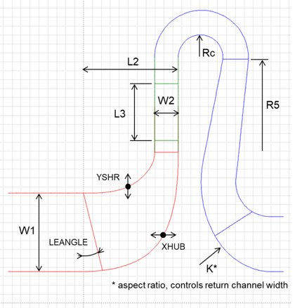 Figure 1: Meridional geometry parametrization
Next, 10 more design parameters are selected as below:
- Impeller
- 3 segment loading at hub and shroud, slope and leading edge loading (4 parameters)
- Trailing edge stacking angle (1 parameter)
- Diffuser Vane
- 3 segment loading, same at hub and shroud (2D geometry), slope and leading edge loading (2 parameters)
- Work, delta rVt from LE to TE (1 parameter)
- Return Channel Vane
- 3 segment loading, hub and shroud slopes linked to reduce complexity (1 parameter)
- Incidence, controlled via rVt difference from diffuser TE to return channel LE (1 parameter)
Thus, in total there are 20 design parameters selected for this sensitivity study.
Sensitivity Analysis
The initial ranges of these 20 design parameters are based on the baseline design values ± variation as shown below:
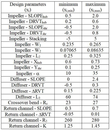
In order to measure the sensitivity, all the parameter ranges are calculated first:
Δxi = xi,max – xi,min (i = 1, 2, …, 20)
A reference design is then generated by setting the value of all the design parameters to 25% of the range:
xi,reference = xi,min + 0.25Δxi (i = 1, 2, …, 20)
Then 20 more designs are generated by systematically increasing or perturbing the value of any one design variable by 50% of the range:
xi,perturbed = xi,min + 0.75Δxi (i = 1, 2, …, 20)
Next, CFD is performed on these 21 designs at 90 and 105% flow rates to measure the efficiency variation from the reference design. 105% is chosen instead of the target 110% to guarantee CFD results near the high flow condition can be obtained for all designs. This methodology produces sensitivity results that are naturally normalized with respect to the range of the input variables, and is also a good compromise between cost and accuracy of performing bi-directional perturbation of the baseline. The variations of the two efficiencies are then combined into a single parameter by inverse distance weighing from the design point.
Ƞcomb = (Ƞ90% + 2*Ƞ105%)/3
Finally, the sensitivity information for the combined efficiency is calculated for each design parameter and plotted as shown in Figure 2, based on which the 10 most significant parameters are selected as the final design parameters for the optimization.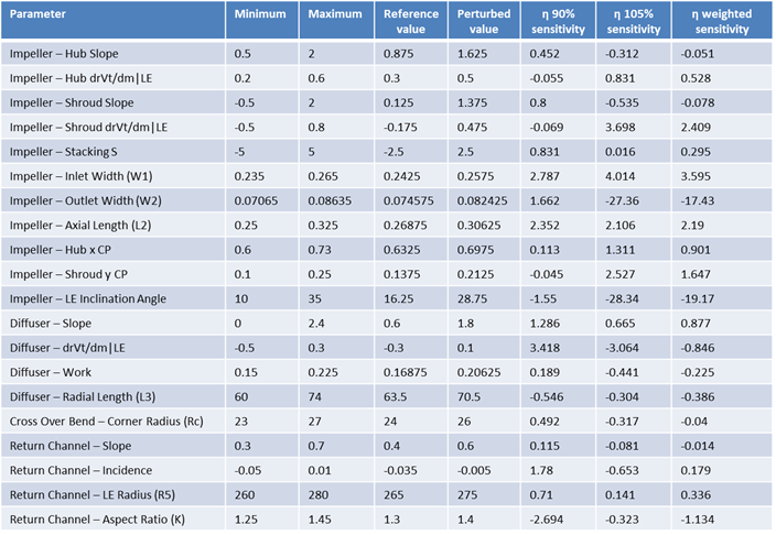
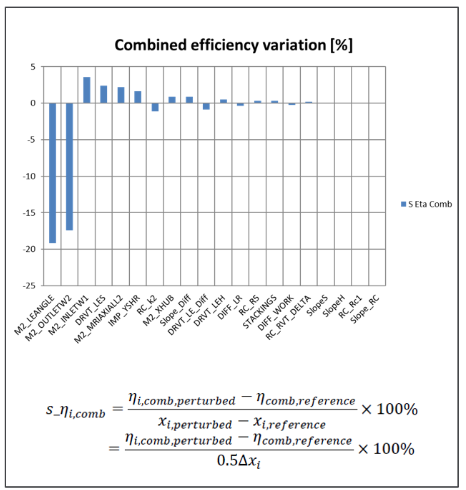
Figure 2: Sensitivity information for the combined efficiency
Response Surface Optimization
Based on the sensitivity information, the ranges and values of the design parameters are updated as follows:
- For the 10 most significant parameters, the ranges are shifted up or down by 25% according to the sign of the sensitivity.
- For the 10 least significant parameters, if the sensitivity is positive then the perturbed value of the parameter is used instead of the reference design value.
Figure 3 table presents the new ranges and values of all design parameters which were selected for optimization.
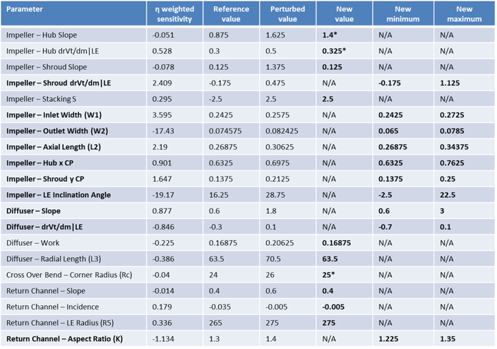
Figure 3: Updated ranges and values of design parameters
Next, for the design of experiments (DOE), 50 designs were generated using Optimal Space Filling Latin-Hypercube Sampling, of which 7 failed to mesh or converge in CFD. Then a Kriging type response surface was fitted to the data of the 43 successful designs, after which MOGA was used to search the design space and generate a Pareto Front for the given objectives and constraints. Here the objectives were to maximize efficiencies at two points that are 90% and 105% of design flow rate, whereas the pressure ratio was not set as a constraint since its variation was very small in the DOE.
Figure 4 displays the Pareto Front showing the trade-off between the two efficiencies, from which an optimal design was selected. Its performance was then validated by CFD simulation, and a comparison of the predicted and CFD efficiency values of the optimal design at both the operating points is also shown alongside, which clearly confirms the high accuracy of the Kriging RSM.
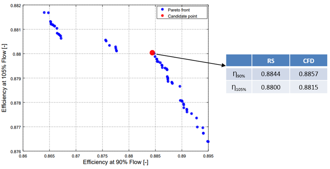 Figure 4: Pareto front with optimal design and accuracy of the Kriging RSM
Figure 5 reveals what changed as a result of the optimization. A comparison of the meridional geometries of the baseline design and the optimal design can be seen, where the major difference is that the axial length and the inducer height of the optimal impeller are increased, and the return channel curvature has changed. Also shown are blade loading comparisons of the different stage components as a result of the optimization.
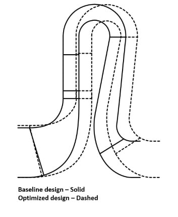
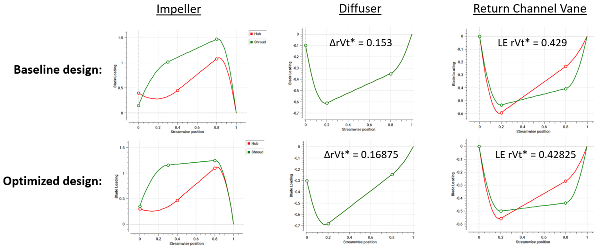
Figure 5: Comparison of meridional geometry and blade loading
The performance map comparison at different flow rates is shown in Figure 6, and the optimal design clearly shows around 1 percentage point improvement in the total-to-total efficiency over a wide operating range, with the total pressure ratio still exceeding the target value of 2 at the design point. Furthermore, the flow field comparison reveals that the flow separation near the baseline impeller and diffuser shroud trailing edge is removed in the optimal design which results in an improvement of the flow behaviour in the cross-over bend.
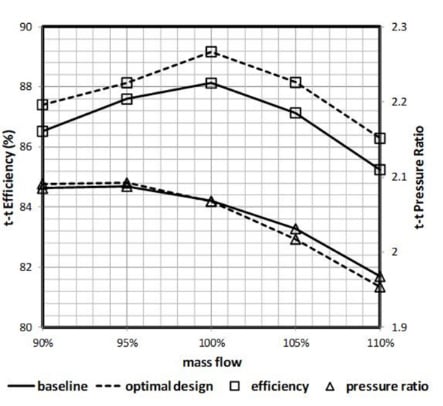
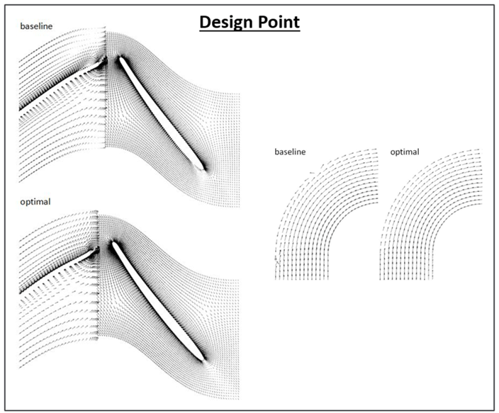 Figure 6: Performance and design point flow field comparison
Conclusion
Using 3D inverse design, the entire stage of an industrial centrifugal compressor with a vaned diffuser and a vaned return channel can be quickly designed and easily taken to a CFD analysis. The meridional geometry and blade loading parameters can be conveniently included in a sensitivity analysis, where each parameter can produce a major change in the design meaning that you can explore a large design space with only a few parameters. The impeller meridional geometry and return channel meridional curvature are found to have the largest effect on the stage performance. The subsequent DOE/RSM based multi-point optimization is very quick where MOGA is used to search the optimal design using Kriging RSM and the objectives are to maximize efficiencies at 90% and 105% mass flow. The resulting optimal design shows improved flow field in all the components and gives approximately 1 percentage point efficiency improvement over a wide operating range based on CFD calculation compared to the baseline design.
References
[1] Zhang, J., Gomes, P., Paralta, A., Zangeneh, M., “Multi-point Optimisation of an Industrial Centrifugal Compressor with Return Channel by 3D Inverse Design”, Turbomachinery Society of Japan, 2017

Book a LIVE demo on the design of a turbomachinery application of your choice.
Our demo is tailored to your specific application and design challenges


Share This Post