Centrifugal compressors are one of the most commonly used gas compression systems across a variety of industries. For a centrifugal compressor, the two most critical components in achieving high stage performance and good flow range are the impeller and diffuser. Therefore, they establish the “baseline” efficiency of the compressor, and so the ability to design these components with high efficiency is very important. Other important factor is the design of the return channel, especially in multi-stage compressors.
Compressor Design Process
The first step in the design of any compressor is to identify the required specific speed regime of the compressor. This will dictate the meridional shape and hence the general flow direction through the pump. For example, a low specific speed compressor is likely to be a radial or centrifugal type, whereas a high specific speed compressor is likely to be of mixed flow or axial type.
From the required specific speed, we can identify the main flow phenomena and loss mechanisms dominant in that particular range (see Figure 1). For example, leakage and secondary flow effects are more dominant in lower ranges, whereas profile/shock losses and corner separation in diffusers take priority in the higher ranges.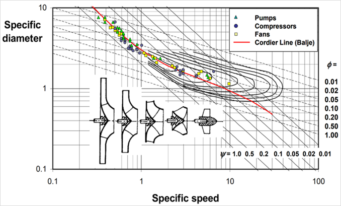
Figure 1: Cordier diagram
From the information above we can use design tools and 3D CFD to investigate our compressor designs, what follows are a set of principal design guidelines based on the fluid dynamics considerations of reducing dominant flow losses for a given compressor.
Over the years ADT has been involved in thousands of compressor designs across all different specific speeds and applications, and has developed considerable fluid dynamic knowledge to systematically design high performance compressors. This article is based on one of ADT’s technical papers that was presented at the Turbomachinery Society of Japan [1].
Meanline Design of Centrifugal Compressor Stage
Below are the different specifications and constraints for the centrifugal compressor stage consisting of an impeller, a vaned diffuser and a vaned return channel, where the target is to improve the performance over the entire operating range from 90 to 110% of the design mass flow rate:
Design point:
Mass flow rate: 5.8 kg/s
Stage t-t pressure ratio: 2.0
Rotational speed: 20,000 rpm
Geometric constraints:
Shaft diameter: 70 mm
Maximum casing radius: Free
Maximum stage axial length: Free
Using the meanline code TURBOdesign Pre shown in Figure 2, it is very easy to enter the above specs and verify that it sits well within the centrifugal region and very close to the Cordier line. This indicates that using these specs, it should be possible to design a centrifugal compressor stage with a high efficiency level, and then the code quickly generates the meridional shape of the entire centrifugal compressor stage in less than a second. It also provides a detailed report including the estimated stage efficiency of about 88.1% and some important dimensions, as well as the required rVt* for the impeller which is equivalent to work coefficient and will be used for the 3D inverse design of the impeller in the next section.
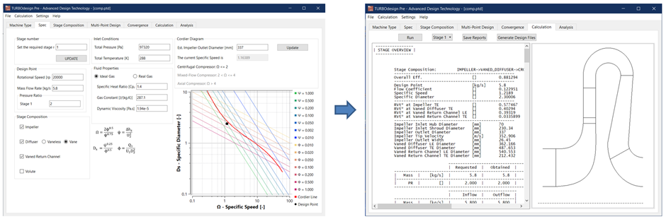
Figure 2: Meanline design of centrifugal compressor stage in TURBOdesign Pre
Software Demo: Meanline Design of a Centrifugal Compressor with TURBOdesign Pre
3D Blade Design of Impeller and Diffuser/Return Channel Vanes
Figure 3 presents the setups for the impeller, the diffuser vane and the return channel vane of the baseline stage in the 3D inverse design software TURBOdesign1, where the meridional shape and blade loading automatically come from the meanline code, and any thickness profile can be imposed. The loading distribution is generally aft-loaded for the impeller and fore-loaded for the diffuser and return channel vanes in this initial design.
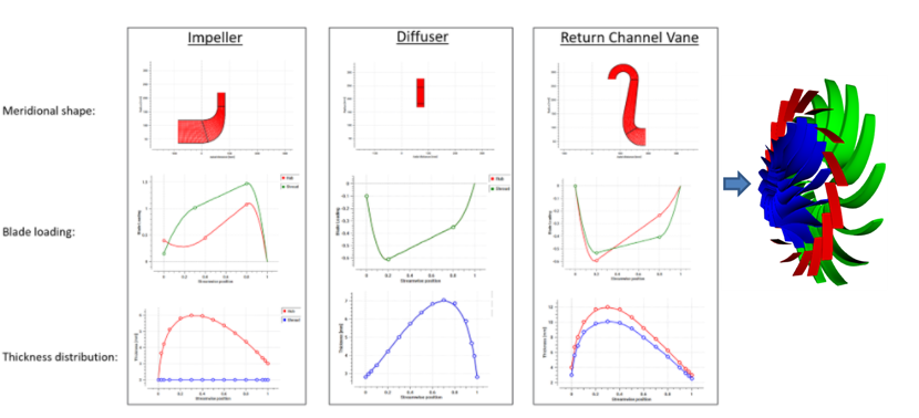
Figure 3: 3D blade design of impeller and diffuser/return channel vanes in TURBOdesign1
Software Demo:
Design of Centrifugal Compressor Impeller, Diffuser and Return Channel Vane with 3D Inverse Design
Baseline Design CFD
Once all the components of the centrifugal compressor stage are ready, a CFD analysis is run on the baseline design to check the performance. ANSYS TurboGrid is used for the fully structured grid of the impeller, diffuser and return channel domains, whereas CFX is used for the flow analysis at five different mass flow rates. As Figure 4 shows, the baseline design is able to hit the pressure ratio target of 2.0 and already has a high stage efficiency of around 88% at the design point, which is in very good agreement with the meanline code prediction of 88.1%. Work coefficient (rVt*) from CFD also shows a close match with the TURBOdesign1 specified values for all the components.
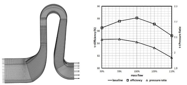
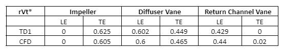
Figure 4: Baseline design CFD results
Flow field analysis confirms that the flow remains well-behaved throughout the compressor stage as shown in Figure 5.
%2c-diffuser-(centre)-and-return-channel-(right)-90.jpg?width=574&height=289&name=Velocity-vectors-in-the-impeller-(left)%2c-diffuser-(centre)-and-return-channel-(right)-90.jpg)
%2c-diffuser-(centre)-and-return-channel-(right)-50.jpg?width=581&height=259&name=Velocity-vectors-in-the-impeller-(left)%2c-diffuser-(centre)-and-return-channel-(right)-50.jpg)
%2c-diffuser-(centre)-and-return-channel-(right)-10.jpg?width=576&height=188&name=Velocity-vectors-in-the-impeller-(left)%2c-diffuser-(centre)-and-return-channel-(right)-10.jpg)
Figure 5: Velocity vectors in the impeller (left), diffuser (centre) and return channel (right) domains of the baseline design
In another article, we present a complete multipoint optimisation methodology for the meridional geometry and the blade loading of the baseline impeller, the vaned diffuser, crossover bend and the vaned return channel using 3D inverse design method, DOE (Design of Experiments), Kriging RSM (Response Surface Model) and MOGA.
References
[1] Zhang, J., Gomes, P., Paralta, A., Zangeneh, M., “Multi-point Optimisation of an Industrial Centrifugal Compressor with Return Channel by 3D Inverse Design”, Turbomachinery Society of Japan, 2017

Book a LIVE demo on the design of a turbomachinery application of your choice.
Our demo is tailored to your specific application and design challenges


Share This Post