Across the specific speed range, compressors are subject to various flow phenomena and loss mechanisms which are dominant in that particular range. For example, leakage and secondary flow effects are more dominant in lower ranges, whereas profile/shock losses and corner separation in diffusers take priority in the higher ranges.
Over the years, ADT has developed considerable fluid dynamic knowledge to systematically design high-performance axial compressor stages. In this article series, we focus on subsonic axial compressors and how to come up with a set of optimal design guidelines to suppress the loss mechanisms specific to them.
Compressor Design Process
The first step in the design of any compressor is to identify the required specific speed regime of the compressor. This will dictate the meridional shape and hence the general flow direction through the compressor. For example, a low specific speed compressor is likely to be a radial or centrifugal type, whereas a high specific speed compressor is likely to be of mixed flow or axial type.
From the required specific speed, we can identify the main flow phenomena and loss mechanisms dominant in that particular range. Using this information, we can use design tools and 3D CFD to investigate our compressor designs; what follows are a set of principal design guidelines based on the fluid dynamics considerations of reducing dominant flow losses for a given rotor/stator.
Meanline Design of Axial Compressor Stage
Figure 1 contains the specifications for the stage, which is a single-stage axial compressor with a rotor followed by a stator. These specs are based on the Rolls Royce HP9 axial compressor, which is a well-documented test case in the literature, and from these specifications, we can see that it actually sits very close to the Cordier line and close to a specific speed of 2, which is where axial machines start. This indicates that using these specs, it should be possible to design an axial compressor stage with a high-efficiency level.
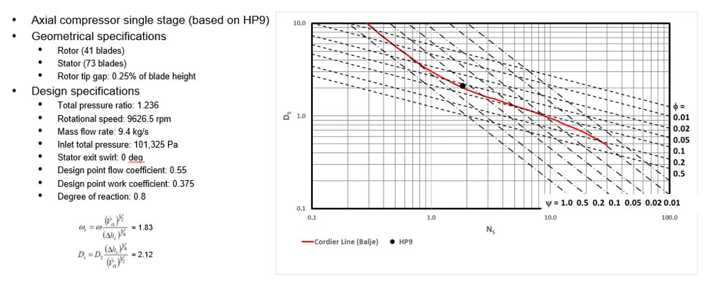
Figure 1: Axial compressor stage specifications and its position on Cordier diagram
Using the meanline code TURBOdesign Pre, it is very easy to enter the given specifications, and then it quickly generates the meridional shape of the axial compressor stage in less than a second. As Figure 2 shows, it also provides a detailed report, including the estimated stage performance and some important dimensions, as well as the required rVt* for the rotor and the stator. These rVt* values for the different components are equivalent to their work coefficients, and they will be used for the 3D inverse design of the rotor and the stator blades in the next section.
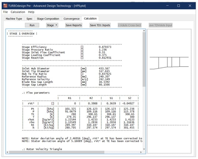
Figure 2: Meanline design of axial compressor stage in TURBOdesign Pre
Software Demo - Meanline Design of Axial Compressor Stage
3D Blade Design of Rotor and Stator
Figure 3 presents the setup for the baseline axial compressor stage in our 3D inverse design software TURBOdesign1, where the initial settings automatically come from the meanline code TURBOdesign Pre. The spanwise work distribution is free-vortex, with zero swirls at the leading edge and a constant value from hub to shroud at the trailing edge. The loading distribution is mid-loaded for this initial design, and then these inputs result in the 3D geometry of the rotor also shown, along with a smooth Mach number distribution throughout the blade surface and the peak value less than 1 for this subsonic compressor.
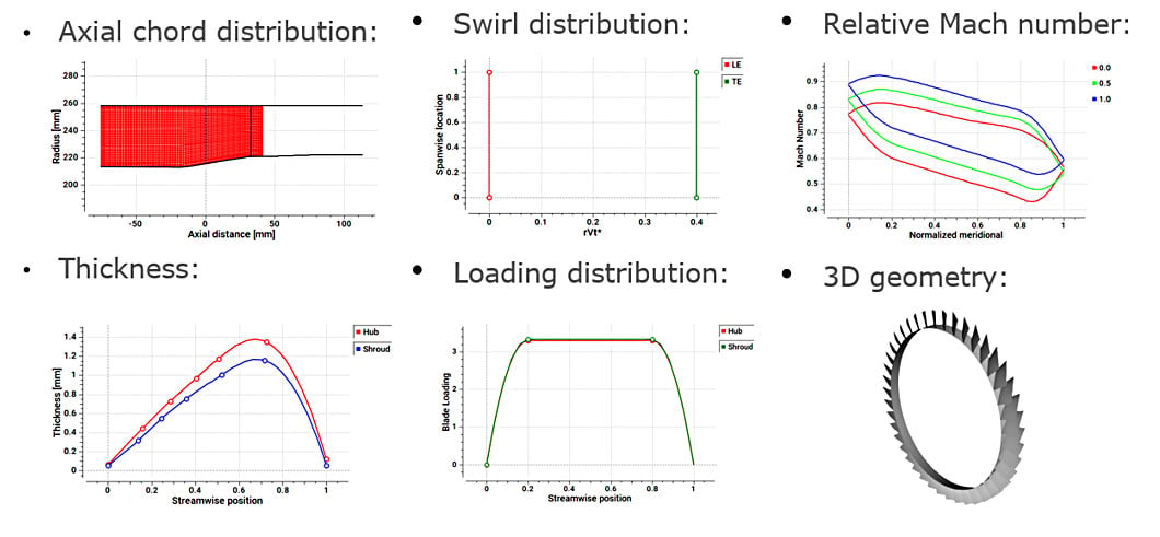
Figure 3: 3D blade design of rotor in TURBOdesign1
Next comes the stator, and again all the settings in Figure 4 automatically come from the meanline code. The spanwise work distribution is again free-vortex, and the rVt* at the stator leading edge is kept close to the rotor trailing edge value which ensures a good matching between them. There is slightly less than zero swirl at the trailing edge in order to compensate for viscous deviation, and the loading distribution is mid-loaded for this initial design. This results in a 3D blade geometry giving a smooth static pressure distribution throughout the blade surface.
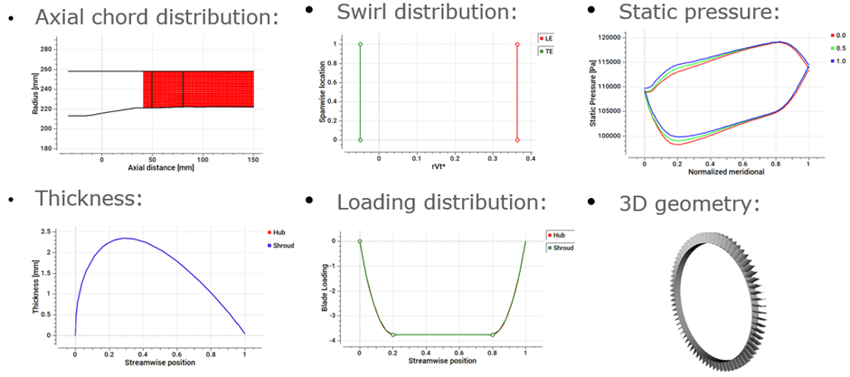
Figure 4: 3D blade design of stator in TURBOdesign1
Software Demo - Design of Axial Compressor Rotor and Stator with 3D Inverse Design
Baseline Stage – CFD Setup
Once all the components of the axial compressor stage were ready, a CFD analysis was run on the baseline stage to check the performance. The boundary conditions used in CFD were chosen to match the inlet conditions and mass flow rate from the TD1 case. As Figure 6 shows, ANSYS TurboGrid was used for the fully structured grids of the runner and the vanes, ANSYS Mesh for the hybrid mesh of the volute and the draft tube, and CFX for the flow analysis.
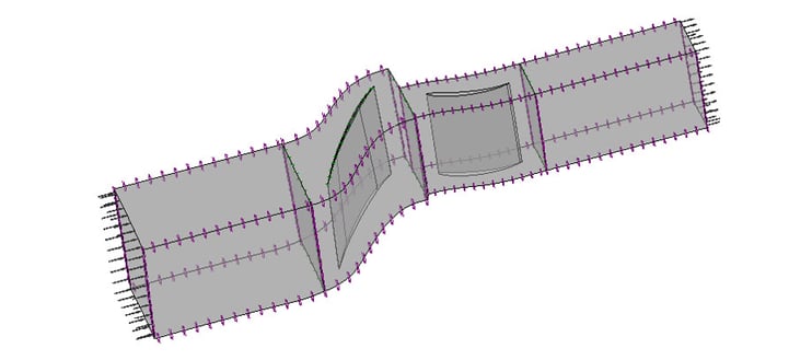
Figure 5: Baseline axial compressor stage CFD setup
Baseline Stage – Results
Figure 6 has the results for the initial stage design, which was seen to choke at about 1% below the design flow rate. And so since TD1 already shows that the rotor is the one with the smaller throat, thus defining the throat of the stage as a whole, its throat was increased by 3%, which is very easy to do in TD1 by simply increasing the leading edge loading like this. And then, as the orange curve shows, this higher throat resulted in sufficient choke margin and stage efficiency at the design point, but the stage total pressure ratio was still falling short of the target value.
In the next step, as the rVt* at the rotor trailing edge in CFD was 10% lower than what we had in TD1, it was raised by 10% in TD1, as shown in Figure 6. TD1 parameters helped to ensure that this does not change the throat and that the diffusion ratio remains below 1.8. When the CFD curve was run again, this time, the stage total pressure ratio was very close to the design point target, along with a rise in the stage efficiency. In this way, a good design was achieved in just a couple of iterations, which was selected as the baseline rotor for automatic optimization.
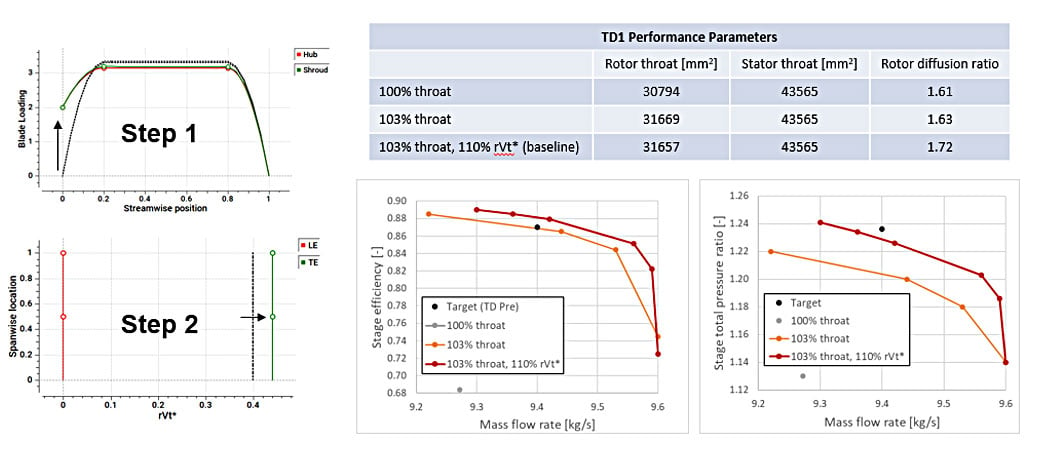
Figure 6: Initial axial compressor stage results
In another article, we demonstrate the use of Optima feature in TURBOdesign1 to automatically optimize the baseline rotor and enhance its performance by improving the profile and tip leakage losses at the same time.

Book a LIVE demo on the design of a turbomachinery application of your choice.
Our demo is tailored to your specific application and design challenges


Share This Post