In another article on the manual design of an axial compressor stage, we showed that there is scope for improvement in the baseline stage, especially in terms of achieving the total pressure ratio target.
This article examines the use of the Optima feature in TURBOdesign1 to automatically optimize the blade loading of the baseline rotor and thus enhance the performance of the stage.
Optimization Workflow
Figure 1 displays the workflow used by the automatic optimization, where the blade loading input parameters are used to generate the blade shape in TURBOdesign1, and then the resulting performance parameters are fed into the optimizer, which basically applies MOGA to drive the solution towards the optimum design.
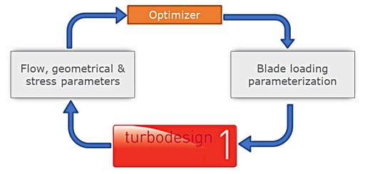
Fig. 1. Workflow used in automatic optimization.
Optimization Setup
The optimization process starts by specifying the range of variation for the input parameters, which are the streamwise loading parameters and the working coefficient at the shroud, because it has an influence on the rotor tip leakage loss, as shown in Figure 2. Whereas by default, the ranges are set to ± 10% of the original value for each parameter, there is a machine learning-based feature in TURBOdesign1 that can provide optimized range estimates for these streamwise loading parameters. This is because we want to explore a large design space but also try and avoid infeasible solutions.
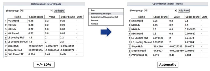
Figure 2: Default (left) and optimized (right) input parameter ranges used in automatic optimization
Figure 3 below shows the constraints that were imposed on the optimizer as follows:
- throat is tightly constrained to ± 1% to maintain the choke margin
- overall diffusion ratio is limited to avoid flow separation
Finally, the optimization objectives are selected so as to minimize the profile and leakage losses in order to hit the desired stage total pressure ratio levels.
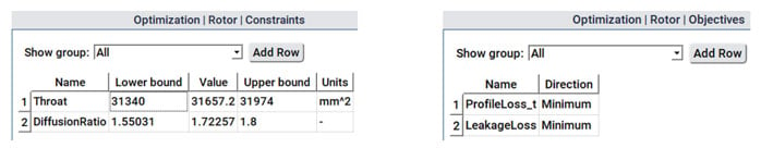
Figure 3: Constraints and objectives used in automatic optimization
Software Demo - Optimization of Axial Compressor Rotor
Optimization Results
Once the optimization run is complete, which is very fast and only takes about 15 minutes or so on a single core machine, all the design candidates can be seen on a scatter plot between the two objectives, as shown in Figure 4. The position of the baseline rotor relative to the candidates may also be noted.
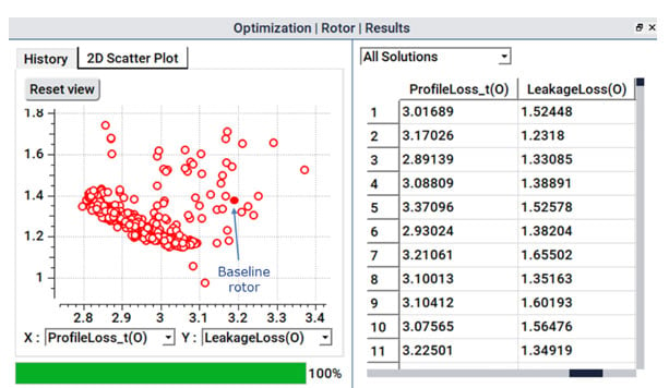
Figure 4: Scatter plot of all optimization designs
Next, as Figure 5 shows, we can choose to see the Pareto front of optimum designs from which it is possible to pick and analyse any design. For the present study, we select a design from near the middle of the Pareto front, which promises a good trade-off between profile and leakage losses, and so we use this design for further analysis and for comparison with the baseline rotor, as indicated in the figure.
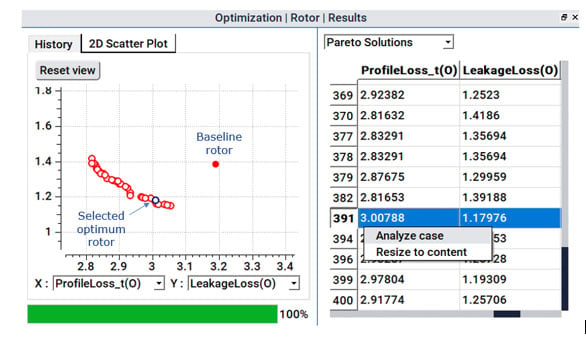
Figure 5: Pareto front of optimum designs
Figure 6 reveals what changed as a result of the optimization. For the spanwise work distribution, compared to the baseline rotor, the optimizer attempts to reduce the work at the shroud in order to suppress the tip leakage. But since the midspan work was kept fixed, the hub work is automatically increased in order to maintain the same overall work as the baseline rotor. Regarding streamwise blade loading, compared to the baseline rotor, the optimizer has tried to make both the hub and shroud fore-loaded in order to reduce the profile loss, and as a result, the optimized blade shape is clearly very different from the baseline rotor, as shown alongside. The Mach number distribution from the inviscid solution plots also looks much smoother compared to the baseline at all the different spans from hub to shroud, and the peak value stays well below 1.
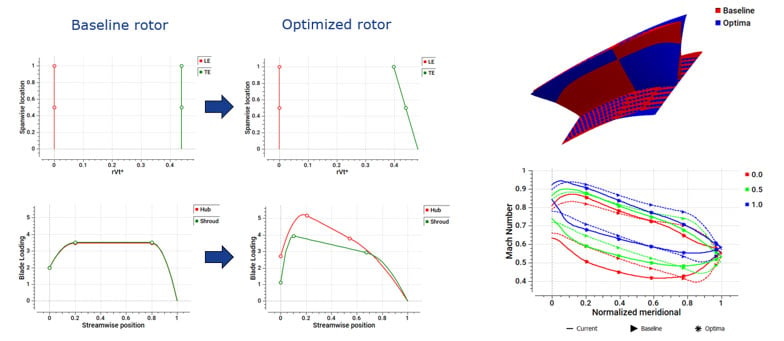
Figure 6: Comparison of spanwise work and blade loading between baseline and optimized rotor
The results for the optimized rotor are presented in Figure 7, where the TURBOdesign1 parameters reveal a significant reduction in the profile and leakage loss parameters as a result of the optimization, with only a slight change in its throat area and diffusion ratio. When stage CFD analysis is performed with the new rotor, there is a notable improvement in the stage total pressure ratio, such that it is now able to exceed the target value. At the same time, the stage efficiency is maintained well above the meanline prediction from TURBOdesign Pre.
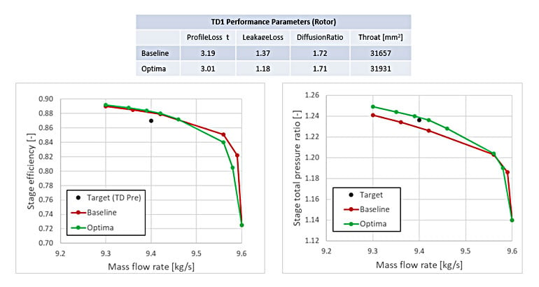
Figure 7: Results comparison between baseline and optimized design
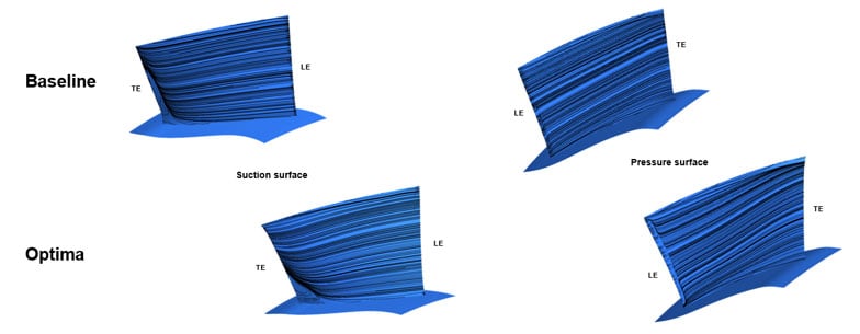
Finally, Figure 8 presents the streamlines on the rotor surface, which confirms a more well-behaved flow, especially near the suction surface trailing edge in the case of the optimized rotor.
Conclusion
There are various types of loss mechanisms in compressors for different specific speed regimes, and it is important to identify those that affect your axial compressor stage. Essentially, with a good knowledge of flow physics gained from CFD and experiments, it is possible to arrive at the optimum blade loading for your specific axial compressor rotor. Our experience has shown that the choice of optimum loading for controlling profile or tip leakage loss has generality and can be applied to other similar applications. For example, we find that for profile loss control, the type of loading that we use for compressors is applicable to all types of compressors, mixed flow and centrifugal and regardless of the compressor speed or size.

Book a LIVE demo on the design of a turbomachinery application of your choice.
Our demo is tailored to your specific application and design challenges


Share This Post