In the past, tandem blades have shown promise in improving the performance of centrifugal compressors. However, the conventional methods for designing them have proved inadequate by themselves and require extra design modifications. In this article series based on a scientific paper which was presented at the European Turbomachinery Conference [1], a successful design and optimization methodology of centrifugal compressor with tandem blade configuration based on the 3D inverse design method is presented.
Tandem-blade centrifugal compressor
Tandem-blade configuration refers to the division of an impeller into two separate blades: an inducer and an exducer. In Figure 1, a full blade conventional configuration can be seen on the left, and on the right hand side we see a tandem blade compressor, where the inducer and exducer blades are clearly visible. The main aim of this study was to investigate how centrifugal compressors with tandem-blade configuration can provide improved performance comparing with full blade configuration.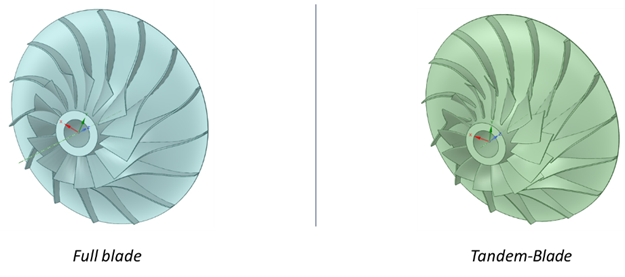
Figure 1: Full-blade and tandem-blade configurations
Motivation
The arrangement of inducer and exducer blades shown in Figure 2 suggests that, in theory, a tandem-blade design should provide performance improvements against a conventional full blade design because:
- there is an alleviation of radial exducer blade workload which can have benefits on operating range, efficiency and exit flow uniformity
- two separate blades can lead to an interruption of boundary layer growth which can possibly improve efficiency and flow uniformity
- the close distance between inducer trailing edge and exducer leading edge results in a jet effect which can act as a flow control method, and can prove to be beneficial to the exducer flow separation
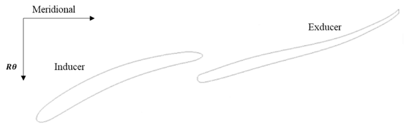
Figure 2: Blade-to-blade view of tandem compressor
This being the case, previous researchers have attempted to use tandem-blade designs to generate designs with high performance. However, although it was extensively studied in axial machines, not much work is found on centrifugal machines. Previous works have reported improvements in discharge flow uniformity, operating range and efficiency, and while some studies did not actually show efficiency improvements, some contradicting results are found in literature.
Furthermore, the current approach in designing these compressors comes from performing a straightforward cut of a full blade design. Evidently, this approach does not necessarily produce optimized results, thus providing further motivation for the present work: A comprehensive method for designing tandem-blade compressors does not actually exist in current literature.
Initial Design
The initial design, with a full blade configuration, that serves as a starting point, is the Radiver test case shown in Figure 3 which is available in open literature. Experimental measurements for this compressor were carried out at the Institute of Jet Propulsion and Turbomachinery at Aachen University in Germany. This compressor has various wedge diffuser configurations with varying gap distance between impeller and diffuser, and a vaneless diffuser configuration as well. In order to decouple the effect of downstream blade components, the vaneless diffuser configuration is used, since the main interest is in seeing how the tandem impeller configuration influences performance.
At this stage, the CFD model to be used during design is established using a mesh sensitivity study and ANSYS CFX for single-phase steady state flow analysis with k-omega SST turbulence model. The requirements for the baseline tandem-blade design, and efficiency objectives for optimization are also determined.
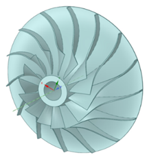

Figure 3: Radiver centrifugal compressor geometry and specifications
Tandem-blade Baseline Design
Using the 3D inverse design method, a tandem-blade design is obtained that has the same pressure ratio as the full blade Radiver compressor at the design point – this is the baseline design. For this, the inverse design solver is run twice as shown in Figure 4:
- First the exducer blade is solved using these inputs:
- the reference wrap angle at the exducer trailing edge
- the blade loading (rVt* and its streamwise derivative)
- Next the inducer blade is solved using these inputs:
- the wrap angle distribution is extracted from the exducer leading edge and a circumferential shift is applied to obtain reference wrap angle distribution at the inducer trailing edge
- the blade loading (rVt* and its streamwise derivative)
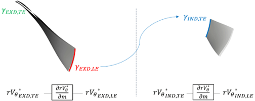
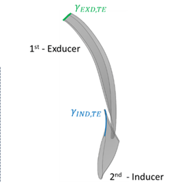
Figure 4: Inverse design method workflow for tandem blades
Regarding the various input specifications for the baseline design, the meridional geometry used is the same as the Radiver compressor as shown in Figure 5. Here the exducer leading edge meridional location is maintained similar to the previous tandem-blade design studies, where the leading edge is placed in a location where the meridional path starts turning from axial to radial direction. The thickness distribution is adjusted between the inducer and exducer blades, keeping the structural stresses same as the Radiver compressor.
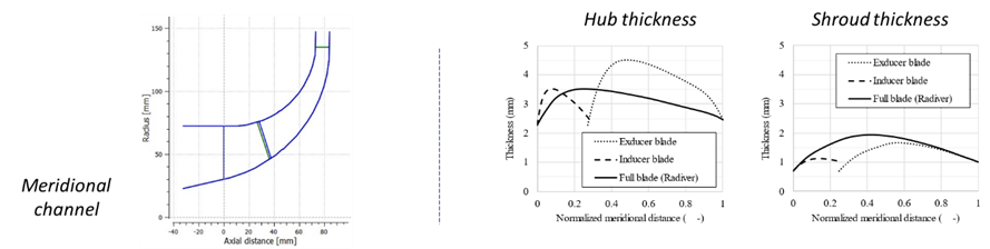
Figure 5: Baseline tandem design meridional shape (left) and thickness distribution (right)
For the blade loading inputs, the leading edge rVt* is zero as the incoming flow has no tangential velocity. At the trailing edge, rVt* is set as 0.705 which provides a design with the same pressure ratio as the Radiver test case. As illustrated in Figure 6, the streamwise blade loading used is similar to previous studies on centrifugal compressors. Three sections are used for the inducer, where the leading edge value is adjusted to reduce leading edge lean and bow ensuring that structural stresses are not over the limit.
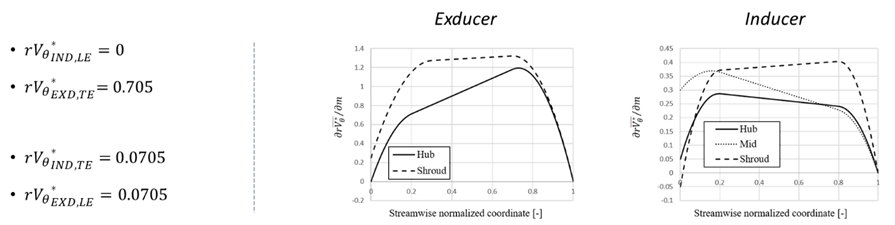
Figure 6: Baseline tandem design spanwise (left) and streamwise (right) blade loading inputs
Finally, the reference wrap angle distribution is defined as in Figure 7. At the exducer trailing edge, the wrap angle is zero from hub to shroud whereas at the inducer trailing edge, the wrap angle is set in a way that a constant distance of 7.5mm is ensured between inducer trailing edge and exducer leading edge.
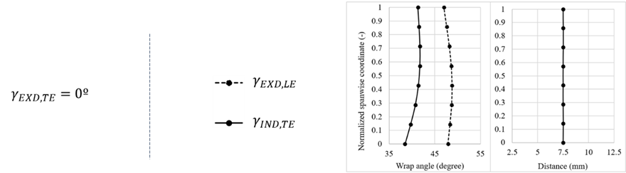
Figure 7: Baseline tandem design wrap angle distribution
In this way, using inverse design, not only is the circumferential shift directly imposed between both blades, but also the amount of work produced by each blade can be adjusted by varying the rVt* values. This provides good control on generating designs in a deterministic way, making it easy to effectively explore the design space.
Baseline Design Performance
With the inputs defined for the tandem-baseline design, the 3D blade geometry is obtained and CFD and FEA analyses are conducted on the same. The full speedline is presented in Figure 8 where the pressure ratio requirement is achieved at all operating points. However, while the efficiency is improved at the high flow rate, no improvement is observed around the design point. Structural analysis reveals that the maximum equivalent stresses obtained are under the defined threshold (the Radiver compressor had a maximum of 340 MPa of equivalent stresses).
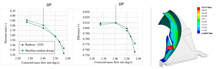
Figure 8: Tandem baseline design performance curves (left) and equivalent stress distribution (right)
In another article, we present an automatic optimisation methodology for the baseline tandem design using 3D inverse design method, DOE (Design of Experiments), Kriging RSM (Response Surface Model) and MOGA with the main goal of increasing the efficiency at the design point.

References
[1] Oliveira, R., Zhang, L., Zangeneh, M., “Tandem-blade Centrifugal Compressor Design and Optimization by means of 3D Inverse Design”, European Turbomachinery Conference 2023, Budapest
Book a LIVE demo on the design of a turbomachinery application of your choice.
Our demo is tailored to your specific application and design challenges


Share This Post