
This blog describes how a Machine Learning algorithm can successfully design a high performance, single component rocket engine turbopump.
The Problem: Rocket turbopumps typically use a separate inducer blade row upstream of the main impeller to minimize cavitation. However, this separated configuration causes problematic flow interactions at off-design conditions, leading to flow separation, backflow, and drooping H-Q curves.
The Goal: The objective is to design a combined, single-component turbopump that eliminates these row interactions and reduces weight, while maintaining the same performance and cavitation margins as a separated design.
The Solution: Unlike standard Artificial Neural Networks that require massive datasets and can hallucinate physically impossible geometries, PEML uses 3D Inverse Design where the inputs explicitly control the fluid physics, such as blade loading.
The Process: The PEML system optimized the combined turbopump using only 13 parameters. By utilizing a Reactive Response Surface algorithm to build an algebraic surrogate model, the system required just 57 simulated designs (amounting to 171 CFD runs over 12.5 hours) to find the global optima.
The Results: The optimized single-component design successfully matched or exceeded the stage efficiency of the baseline separated design across multiple operating points. Furthermore, it achieved the same or better cavitation margins. This demonstrates that PEML offers highly accurate, paradigm-shifting performance gains for turbomachinery at a fraction of the computational cost.
What is Physics-Enhanced Machine Learning (PEML)?
AI seems to have the answer to many problems, but can it be applied to the problem of designing something as complex as a turbomachine? In theory, and according to the architecture of an Artificial Neural Network (ANN), with enough training data the network should be able to predict the performance of any given blade geometry under any given operating conditions. There are immediately two intractable issues with applying this in principle.
Firstly the enormous amount of training data (in the form of CFD simulations) that need to be generated in order to train the model. Thinking about the number of geometric parameters alone, and the curse of factorial dimensionality that turns the design space into a multi-dimensional giant, plus multiple operating points, plus the non-linearity of fluid flow means that many thousands of training points need to be created. Which does not look like a good value proposition when compared to simple trial and error.
Secondly the model is still predicting the performance of a given blade shape. So the shape is the input and the required performance is the output. This is the wrong way around. We should be able to define the performance characteristic that we want, and the system finds the blade shape that delivers that.
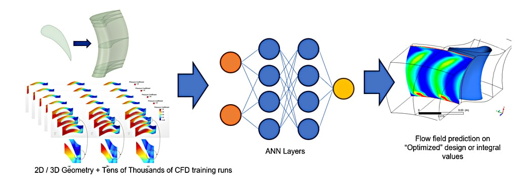
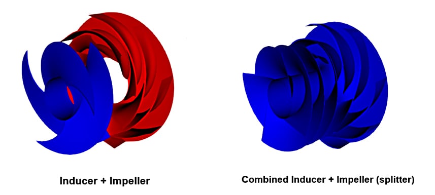
Figure 1: ‘Traditional’ ANN architecture relies on tens of thousands of training datapoints, but can still ‘hallucinate’ complex flow physics
Physics Informed Neural Networks (PINN) seem to have a solution to this problem, by embedding the governing equations into the nodal weights at randomly scattered ‘co-location points’ thought the fluid domain, PINNs do not suffer from hallucinations or impossible physics that arise in ANNs. However PINNs do suffer from a phenomenon called spectral bias. By their mathematical nature, PINNs prefer to learn smooth, low-frequency patterns first and struggle to capture sharp, high-frequency changes seen in turbulent boundary layers and transonic flows. Trained PINNs are also incredibly specific and do not generalise well. A change in boundary condition will mean a whole new training dataset.
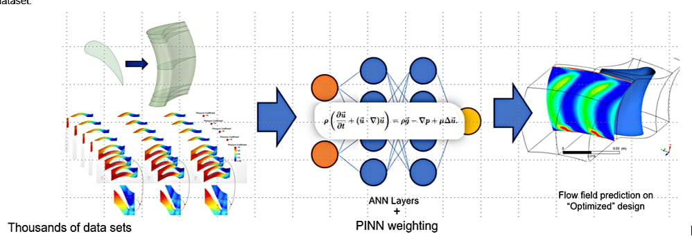
Figure 2: PINN architecture seems to have a solution to the hallucination problem, but is not good at resolving large gradients in a flow field
The real solution is Physics-Enhanced Machine Learning (PEML). This is a system developed by Advanced Design Technology (ADT) where the inputs to the problem are controls on the physics of the flow in the blade passage. The outputs are blade shapes. Thus what we want from the design (flow, performance, speed etc) is a controlled value, the solutions just attempt to answer that requirement in different ways.
The system can’t hallucinate because the process of getting outputs from the input is physics-bound, all variations on the input recipe result in a valid output candidate - it just might not be the most efficient or multi-objectively optimal (‘Pareto-optimal’). We also do not need a large training dataset. Because of the efficiency of the Inverse design parameters and the fact that the system as it selects training point candidates, is ‘physics-aware’, typically less that 70 candidate designs are required.
Once the training data is assembled, the system constructs a surrogate model - which is essentially just an N-dimensional surface fit over the data. Finally the surrogate model is searched (this is incredibly quick, as we are using algebraic surrogate data) for the global optima.
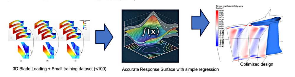
Figure 3: PEML requires a small training dataset and cannot hallucinate
How to use PEML to design a rocket turbopump?
Turbopumps deliver liquid fuel and oxidizer into the combustion chambers of rocket engines.The have to operate a very high delivery head to overcome the combustion pressures, and be compact and lightweight to reduce parasitic weight. This means that they run at high rotor speeds.
However, a high speed and the fact that the working fluids have high vapour pressures gives rise to the tendency of all rocket turbopumps to cavitate. In order to eliminate cavitation to a certain degree, an inducer blade row is often placed upstream of the main impeller. The inducer, acting as a pre-pump, increases the pressure of the fluid by a sufficient amount to minimize cavitation and improve the performance of the impeller. They are sometimes expected to sacrifice themselves to safe-guard the impeller blade from cavitation.
However in these ‘separated’ designs, there is an interaction between the inducer TE and the impeller LE, particularly at off-design conditions. This interaction often leads to unfavourable flow phenomena like a drooping H-Q curve, flow separation, and backflow. By moving to a combined design, this interaction is completely eliminated.
Moreover a combined design has a lower number of components, further reducing weight and size, which is a critical factor in increasing the thrust-to-weight ratio.
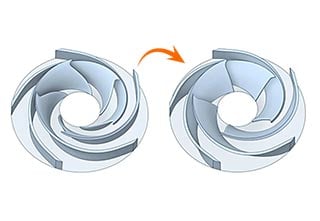
Figure 4: Inducer and Impeller with the combined version on the right with the Impeller (splitter)
So the challenge is to design a ‘combined’ single blade row pump impeller that has the same performance and cavitation margin as the equivalent ‘separated’ design.
Baseline Separated Design
The baseline separated design is selected from an existing LH2 turbopump case. It is a 4-bladed inducer and an 8-bladed impeller design. From the CAD model, we create a computational model and numerically simulate the pump stage performance to obtain its performance characteristics. The results show this pump has a high stage efficiency from from 85% to 115% of the design point.
The PEML will use the same design specifications (stage head and flow rate) to design a combined version of this turbopump.
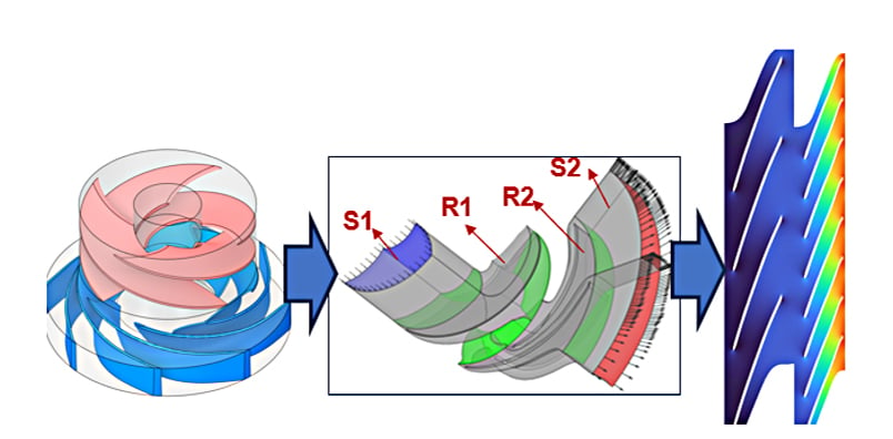
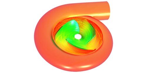
Figure 6: The baseline separated design, realised in CAD and run through CFD simulation
Baseline Combined Design
In ADT’s flagship design software TURBOdesign1, We create a combined design in the same meridional outline as the separated design and add an independent splitter. Then run through high-fidelity simulation to find the comparative multi-point performance .
One of the great advantages here is that all designs can be automatically simulated using CFD through the CAE Integration module within TURBOdesign1. The computational grid, numerical simulations, and post-processing were all handled automatically to generate the performance characteristics of the combined design.
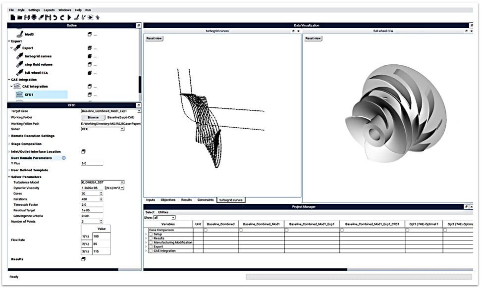
Figure 7: The baseline combined design, created in TURBOdesign1
Looking at the results, the combined design does show a lower stage efficiency compared to the separate design. However, the head matches perfectly at the design point and follows the exact same trend across all other flow rates.
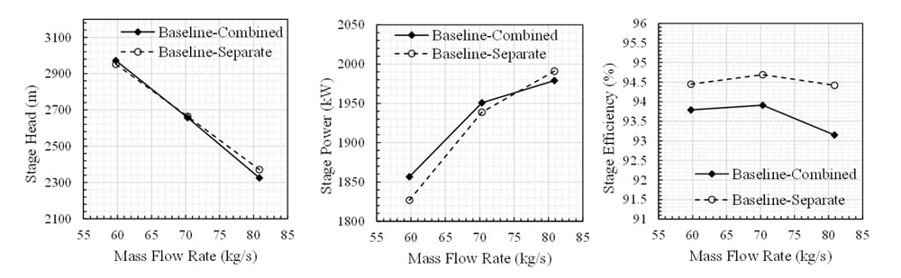
Figure 8: The baseline combined design performance compared to the baseline separated design
We also ran two-phase simulations on the separated and combined designs to evaluate their suction performance through the head breakdown curves as the inlet pressure is reduced.
As you can see on the plot, the combined design loses performance at higher values of NPSH much earlier than the separate design. By looking closely at the flow field, we discovered the root cause.
The combined design has a low throat area at the impeller main blade. This restricts the flow, causing local flow acceleration and a subsequent drop in static pressure. Ultimately, this leads to early cavitation inception and its rapid propagation.
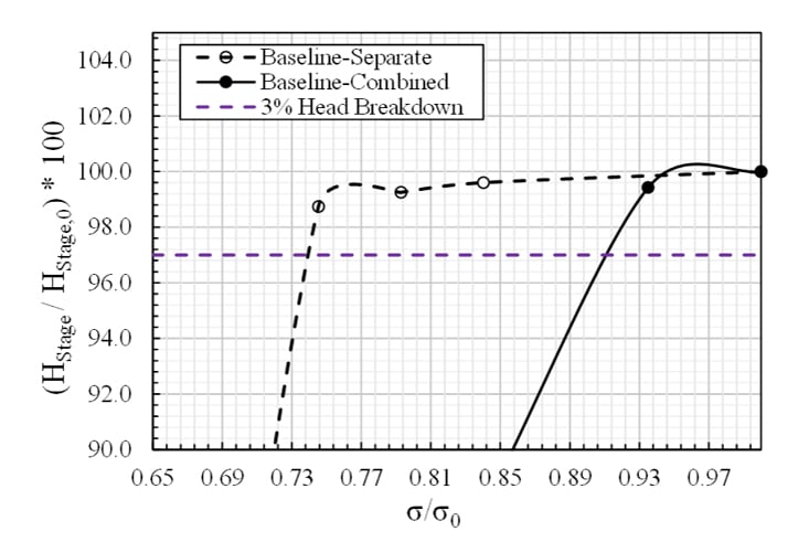
Figure 9: Head breakdown curve of baseline separated and combined designs
Physics-Enhanced Machine Learning finds the Optima
We can state our objectives for this study as “Improve pump efficiency at all 3 operating points, improve cavitation margin to be comparable to the separated configuration”.
By leveraging the power of 3D Inverse Design we only need 13 parameters to fully describe the blade characteristics and generated a richly varied design space. 4 of these describe the position of the main blade and splitter leading edge. 1 parameter defines the amount of blade wrap (or ‘stacking’ angle) . The other 8 parameters describe the distribution of blade loading across the main and splitter blade. For more information about how blade loading inverts and unlocks the turbomachinery design process. See our previous blog: "Blade Loading, Inverse Design and Shape Parameterisation”.
Our Physics-Enhanced Machine Learning systems intelligently explores this 13-dimensional design space, firstly as a latin hypercube sample, then through targeted motion towards the global optimal. We call this process the ‘Reactive Response Surface’ as it is continually updating the fit of a surrogate response surface as more data is added. For more information on this method, see our previous blog: “What is Reactive Response Surface”.
The PEML requires just 57 different candidate designs to build an accurate model of the design space. Each candidate runs 3 operating points (85%, 100% and 115% of design volume flow rate) so that is 171 CFD runs, which took 12 ½ hours on a standard 32 core deskside workstation.
Once the problem is defined TURBOdesign1 automatically takes care of all the CAD generation, meshing, pre-processing, solving and post-processing. The user just waits for the results to arrive back in the TURBOdesign1 GUI. Because the stage head is an input to the system in TD1, all of the designs generated, even with large geometric variations, will meet the target head. We can see that the head variation in the design matrix is very small.
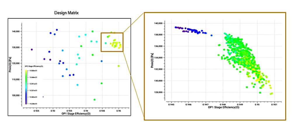
Figure 10: 2D view on the design space (left) and the surrogate model pareto front constructed in the highest performing region of the design space (right)
The result is that the PEML presents a multi-dimensional Pareto front of optimal designs. All the candidates on the front are optimal - they just pay-off the competing objectives in different ways. We can select any number of designs from the Pareto front and run them back though the CFD simulation to check their performance, and the accuracy of the PEML prediction.
Performance assessment of designs found by PEML
The designs selected from the surrogate model Pareto font are assessed using high-fidelity CFD in 2 phase simulation.
Figure 11: Pareto optimal designs selected from the multi-dimensional Pareto front and sent for high-fidelity simulation analysis
The first finding is that we have regained and in some cases, exceeded the efficiency of the separated design, whilst retaining the head-flow curve characteristic across the flow range.
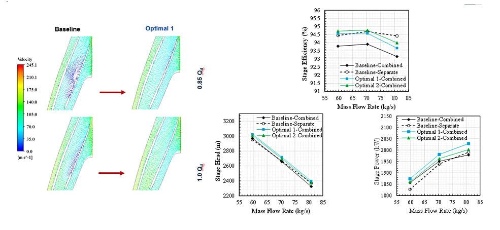
Figure 12: Performance of the optimal combined designs , compared with the original separated design
Then when we look at the head breakdown curves, the cavitation margin is the same as, or better than the separated design. This is a great result and it shows that we could directly swap out our complex separated stage, for a simpler, lighter, cheaper alternative with the same or slightly improved performance.
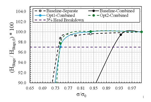
Figure 13: Head-breakdown-the-optimal-combined-designs
We also see that the accuracy of the PEML surrogate model (basically the ‘training weights’) is very good. When the PEML predicts an efficiency of 98.48% , the actual result returned by CFD is 94.58% . The correlation is similarly high across all the operating points. This tells us that the fit of the data to the surrogate model is very good and the predictive power of the surrogate model is very high.
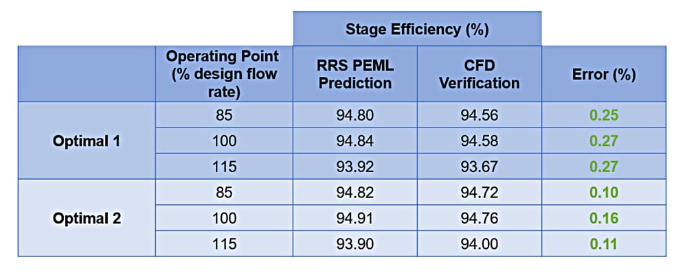
Figure 14: Error check and validation of the surrogate model when compared to running the selected optimal points in CFD
This accuracy comes from the ‘Reactive’ part of the learning model, in that it concentrates the high-fidelity simulations in the area where it already knows that the optima lie, so the discovery of the optimal region of the design space is self-reinforcing.
Physics-Enhanced Machine Learning is the way to paradigm shifting performance gains in turbomachinery
No other ‘AI’ system comes close to ADT’s Physics Enhanced Machine Learning system for the specific problem of radically improving turbomachinery design. The inputs to the system are controlling the flow physics and the outputs are designs that always meet the principle performance parameters. And all for a fraction of the total cost traditionally associated with large scale, high-fidelity optimisation studies involving complex geometry and flow interaction.
This Physics-Enhanced Machine Learning system, available right now, can be applied to pump stages of all types. And to all other types of turbomachinery: fans, compressor stages, turbines, blowers. In any flow regime or working fluid.
Book a LIVE demo on the design of a turbomachinery application of your choice.
Our demo is tailored to your specific application and design challenges


Share This Post