This blog describes how tools from Advanced Design Technology (ADT) use a combination of 3D Inverse Design and Machine Learning (specifically "Reactive Response Surface + CAE") to rapidly design high-performance wastewater pumps. The primary challenge in wastewater pump design is balancing conflicting requirements: high hydraulic efficiency, the ability to pass large solids, and preventing cavitation. By using Machine Learning, engineers can explore vast design spaces to find optimal solutions that meet strict non-clogging constraints in a matter of hours.
-
TURBOdesign Pre provides the starting point for stage design
-
3D Inverse Design - the enabling technology for Machine Learning
-
Creating a seed design and specifications for running CFD within the ML training
-
TURBOdesign1 creates design choices from the Machine Learning solution
-
Re-using the training dataset to optimize the pump design for a new set of objectives
-
Conclusions - Machine Learning for turbomachinery design is now a reality
Why invest in wastewater pump design optimization?
Handling water and wastewater consumes around 4% of the world’s total electricity. For local municipalities, the burden is even heavier; water and wastewater processing often accounts for 30% to 40% of their total energy bill. In this context, the wastewater pump is a critical lever for energy conservation. Every percentage point of hydraulic efficiency gained through advanced impeller design represents a direct reduction in the carbon footprint of urban centers. Moreover, pumps that can pass greater amounts of solid matter are at greatest advantage in deployment to scalable water-recycling applications.
This drive for sustainability is fuelling a massive transformation in the market. As industries race to meet net-zero targets and modernize aging infrastructure, the global demand for energy-efficient, non-clogging pumping solutions is surging. The market for wastewater pumps is projected to grow significantly at a steady CAGR of 5%.
Thus the design of wastewater pumps is driven by the conflicting requirements of efficiency, non-clogging capacity and the ability to work with low values of required Net Positive Suction Head (NPSHr) to preserve and improve cavitation margin. In this blog we look at how Advanced Design Technology’s Reactive Response Surface + CAE technology is driving better pump design through Machine Learning, and we’ll see how a highly efficient and optimised design, across multiple operating points, can be arrived at in just a few hours when we let the Machine Learning system take the reins.
TURBOdesign Pre provides the starting point for stage design
Before the Machine Learning system can get to grips with optimizing a design, we need to establish a baseline sizing and component integration for the stage, based on the most basic requirements of the pump:
-
How much flow
-
How much head (pressure rise)
-
How fast will it spin
-
And crucially, for wastewater pumps, the minimum solid passage size (a sphere of a given diameter
Plugging these numbers into TURBOdesign Pre, plus some other details about the working fluid, the inlet conditions, and how the stage should be configured results in a complete 2D stage design for the rotor and volute. Within seconds we also get an approximation of the characteristics across the speed and flow range. Using this starting point, we know that we are on the right track for a well conditioned, correctly sized machine.

Figure 1: TD-Pre’s custom module for wastewater pump design changes the meridional path shape depending on the minimum solid pass-through size

Figure 2: TD-Pre generates a stage characteristic within seconds of specifying the general required performance parameters
3D Inverse Design - the enabling technology for Machine Learning
In a previous blog, we showed how ADT have constructed and assembled the necessary building blocks to enable a turbomachinery Machine Learning system that can rapidly and efficiently home in on optimized designs. In that case the application was an axial fan, but as you’d expect, the system can be configured to work on any turbomachinery design challenge. Very briefly, the advantages of 3D Inverse Design over conventional design are:
Minimization of input parameters: Just a handful of parameters are required to describe extremely complex and varied 3D blade shapes.
Parameter leverage - small changes to parameter values can drive large blade shape changes.
Designs are guaranteed to meet duty points. As the required performance is the input and the blade shape is the output, 3D Inverse Design does not waste effort creating non-compliant designs that do not meet the basic performance requirements.
Designs can be assessed for performance without reverting to high-fidelity, and high-cost CFD simulation.
Coupled with ADT’s Reactive Response Surface (RRS) optimizer technology, vast and complex turbomachinery design spaces can be explored and exploited in a matter of hours on standard desktop hardware.
Including the volute in the performance prediction
The volute and its interaction with the rotor must be included in the simulation and analysis if we are to achieve a meaningful improvement in complete stage performance. It is no longer acceptable to design and optimize a rotor in isolation, as any performance improvements seen in the rotating part can quickly be wiped out if the volute is not matched to the rotor and the whole thing has not been considered as a system. For this reason TD1 Machine Learning for pumps gives the option (although we would always recommend using) to include the volute geometry in the analysis.
The advantages here are twofold - firstly the performance of the stage is the ultimate arbiter of success, so , although it is a bit more computationally expensive to run full stage simulation , it really should be used as the metric. Secondly the volute should be matched. As the rotor shape changes and the way that it delivers flow into the volute varies the volute shape should be recalculated to take account of this. In TD1 this update and recalculation takes place automatically, so the rotor and volute are linked as an integrated system, not two standalone components.
For a wastewater pump there is a further consideration once the volute is included and that is solid passing through the volute scroll. TD-Volute now include a feature to specify minimum clearance under the tongues - so ensuring that no solids below a maximum clearance side will clog in the volute.

Figure 3: One parameter controls the volute tongue clearance and the volute shape is automatically recalculated to take account of this
In this case we know that the volute entry (r0) is at r=140.5mm (from TD Pre meanline), so we just set the clearance radius (rc) to 193mm, which gives 52.5mm of passage clearance

Figure 4: Setting the volute tongue clearance to a specific value in TURBOdesign Volute
Creating a seed design and specifications for running CFD within the ML training
After specifying the performance and volute requirements, a ‘seed’ 3D rotor design can be immediately created in TURBOdesign1. This is an inverse design and immediately allows access to 3D blade loading design parameters - which are what drive the 3D blade shape change.

Figure 5: 3 Bladed ‘seed’ rotor design created in TURBOdesign 1 from the specifications from TD-Pre
We now set up a CFD simulation to discover the performance at the off-design points, for this study we’ll look at 85% and 115% flowrates. It’s an important point to understand that, because the performance requirement is the input to Inverse Design, we cannot use it to run off-design performance prediction - otherwise the Inverse Design algorithm would take the off-design operating conditions and create a new blade shape best suited to delivering those requirements - so making off-design into on-design. Fortunately TD1 integrates seamlessly with major CFD systems including ANSYS-CFX and Simcenter STAR-CCM+ and Cadence Fine Turbo . So just a couple of mouse-clicks have the CFD runs underway. Domain creation, meshing, pre-processing (including the joining of the rotor and volute domains), running the solver and post-processing are templated, scripted processes, managed by TD1, so we get consistency of analysis time after time.

Figure 6: TURBOdesign1 sets up complete stage CFD simulations across multiple operating points in just a few mouse clicks
With the pump stage performance requirements defined, and a framework in place for generating high-fidelity CFD solutions of the stage, we are ready to create a machine learning system to discover optimum designs.
Pump optimization via Machine Learning
Inputs
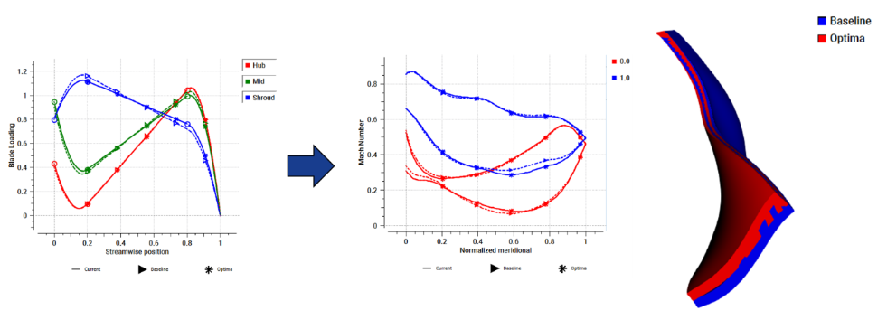
The power of 3D Inverse Design means that we can use just 8 input parameters to create a large and rich design space wherein we hope to find an optimal ‘non-clogging’ design. The parameters control the distribution of blade loading (so the distribution of specific work) across the blade surfaces. TD1 also uses an ML algorithm to recommend appropriate ranges for your input variables, so that the design space is not too wide, resulting in ‘impossible’ designs, nor too narrow which might preclude a genuine, usable optimum being found.
Constraints
We tell the Machine Learning algorithm that the design must pass a 50mm solid - this is the only constraint, and designs that do not meet this will not be considered. Moreover, the Reactive Response Surface algorithm knows to move away from regions of the design space that violate constraints, resulting in a more efficient use of exploratory resources.
Objectives
What do we want from this machine? Because we are integrating multi-point CFD runs into this study we can choose CFD results from off-design points as objectives. In TD1 we tell the optimizer to minimize NPSH and maximize stage efficiency at different operating points. Note how, by setting objectives and constraints in this way, we are abstracting ourselves from the details of hydrodynamic design. We don’t care how the Machine Learning system solves this problem, with a combination of different blade curvatures and shape control that influences the local flow features, we just care about the outcome.
Once we have set the optimizer meta-parameters (number of iterations, number of new designs added per iteration, and some settings governing the surrogate model used within Reactive Response Surface + CAE) the optimizer can be run to find the optimum solution. In this case the study took 12½ hours to run on 12 workstation cores.
TURBOdesign1 creates design choices from the Machine Learning solution
Reactive Response Surface + CAE uses a combination of low- and high fidelity simulation, surrogate models and a genetic algorithm to discover the optimum designs.
It uses CFD to create a small, but highly targeted training dataset, which is specific to this geometry, application and objectives. So, for example we can look at the Head vs Flow curve of all the stage designs in the training dataset, demonstrating that this Machine Learning system is trained on data specific to this application.
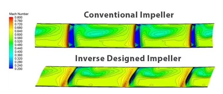
Figure 7: Head vs Flow curves for all design matrix candidates
With this training data we can build a surrogate mode and discover the Pareto front of optimal design that pay-off the 3 objectives against each other (so a 3 dimensional objective space) Every point on this front is an optimal compromise between the 3 objectives. So we can select a final design based on what priorities we choose - effectively weighting the objectives based on relative importance. At this stage, these are all surrogate model points, so have not been ‘realized’ as actual blade shapes and assessed in higher-fidelity simulation.

Figure 8: The optimizer creates a Pareto front of competing objectives. (this a 2D view of a 3D objective space)
Selecting a point on this Pareto front gives us an optimized, non-clogging design. With a single mouse click we can instruct TURBOdesign1 to run any selected point from the Pareto front back through the CFD multipoint analysis to confirm performance. We also can compare the error between the surrogate model prediction and the high-fidelity simulation of the selected design.

Figure 9: Accuracy of the Surrogate model compared to running the selected design back though CFD simulation
Re-using the training dataset to optimize the pump design for a new set of objectives
A key feature of the Reactive Response Surface + CAE system is that we can re-run a new optimization study, with new objectives and constraints, but using the training data in the design space that were discovered by the first pass optimization. This means we can complete a whole new optimization study in seconds, without having to generate new training data.
In this case we ask the Machine Learning system a new question - generate a non-clogging design where the low flow (85%) performance is optimized for efficiency, head and cavitation margin.. The 50mm diameter solid passing constraint remains in place.
Reactive Response Surface + CAE re-runs the optimization study in a few seconds and comes up with a new design space, and a new Pareto front which shows the pay-off between the new objectives.
The figure below shows how a new Pareto front for low flow performance (in orange) can be constructed, and how this exceeds at all points, the optimized candidates from the original study (in blue) when looking at the low flow point performance.

Figure 10: Pareto front on re-run optimizer study for new objectives
When we choose a design candidate from this front, and run the resulting geometry though a CFD stage prediction we find that exactly what we have asked for has happened - the low flow performance has improved in all respects - but at the expense of performance elsewhere (that the ML system does not ‘care’ about in the second pass), and we can compare the 2 optimizer strategies that we have employed.

Figure 11: Re-optimization allows the design objectives to be changed whilst using the same training dataset
Pareto optimal designs using either strategy are guaranteed non-clogging designs (because they do not violate the Machine Learning constraint) an example of which is in the figure below:

Figure 12: Wastewater pump optimal design proven to be non-clogging for 50mm dia particles
Conclusion - Machine Learning for turbomachinery design is now a reality
In this blog we have shown that, in just a few hours on a standard workstation, Reactive Response Surface + CAE can create a constrained, high performance wastewater pump redesign using the 3D Inverse Design approach. Moreover that design can be used to re-run the optimization for a new set of objectives and/or constraints, using the same set of training data.The Reactive Response Surface + CAE model is an ideal method for delivering optimal designs in a multi-point, multi-objective design space, and for a fraction of the total cost traditionally associated with large scale, high-fidelity optimisation studies involving complex geometry and flow interaction.
Schedule a live demo tailored to your turbomachinery application.
We'll show you how to solve your specific design challenges.

Share This Post