
Designing a compressor stage as a whole, with the rotor, diffuser and volute optimized together, has long been out of reach for most engineering teams because of the computing cost. This article shows how Physics-Enhanced Machine Learning (PEML), driven by 3D Inverse Design, changes that. Using just 9 physics-based design inputs and 45 training designs, a complete industrial compressor stage was optimized across three operating points in 77 hours on 36 CPU cores. The result was a +1.1% absolute gain in stage efficiency in one candidate and a +5.7% increase in choke flow in another.
The Problem: Optimizing an entire industrial compressor stage (rotor, diffuser, and volute) using conventional 3D CFD is historically computationally prohibitive due to dozens of geometric variables and complex fluid coupling.
The Solution (PEML): Instead of using arbitrary CAD shapes that lead to unphysical results or require tens of thousands of training runs, Physics-Enhanced Machine Learning (PEML) pairs 3D Inverse Design with automated aerodynamic volute matching. The design inputs directly control the fluid physics (blade loading and meridional dimensions), mathematically ensuring that every candidate delivers the required specific work and eliminating non-viable designs
Workflow & Setup:
-
Reduced the full-stage parameter space to just 9 physics-based design inputs.
-
Required a training Design of Experiments (DoE) of only 45 candidate designs evaluated across 3 operating points (design point, near-surge, and near-choke).
-
Completed the entire 135 CFD run optimization campaign in just 77 wall-clock hours on 36 CPU cores.
Validation & Results:
- Surrogate Accuracy: Prediction error was under 0.25% for efficiency and virtually zero for pressure ratio.
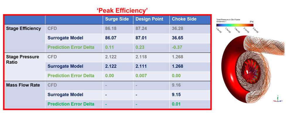
- Candidate 1 (Peak Efficiency): Achieved a +1.1% absolute gain in stage efficiency while maintaining map-width.
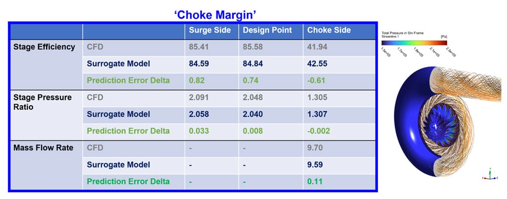
- Candidate 2 (Choke Margin): Expanded flow capacity at choke from 9.18 kg/s to 9.70 kg/s (a +5.7% expansion), significantly widening the operational envelope.
- Why is full compressor stage optimization so challenging?
- How does 3D Inverse Design speed up compressor optimization?
- Meanline Sizing and 3D Inverse Design
- How does automated volute matching reduce design variables?
- What is Physics-Enhanced Machine Learning (PEML)?
- Automated CAE Integration & Training Data
- Multi-Objective Optimization Targets
- Interrogating the Pareto Front & Selecting Candidates
- What results did the optimized compressor stage achieve?
- Key Takeaways
- Conclusion
Why is full compressor stage optimization so challenging?
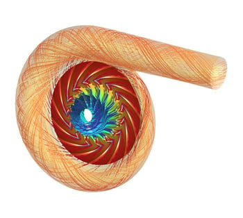
Figure 1: Flow visualisation in a compressor stage
The flow through a compressor rotor, diffuser and volute are closely coupled. Meaning that a very efficient rotor may not perform as the most efficient stage if the components are not matched. Flow non-uniformities leaving the impeller directly impact diffuser recovery, while the circumferential static pressure distortion imposed by the volute feeds upstream, altering blade loading and choking margins. However, when considering the optimization of the entire stage, adding the volute geometric design parameters along with the rotor geometric design parameters would traditionally greatly increase complexity and computational load.
Historically, full-stage aerodynamic optimization has been computationally prohibitive. Parameterizing the full 3D geometry of both the rotor and volute requires dozens of geometric variables. Exploring such a massive design space with high-fidelity, 3D Computational Fluid Dynamics (CFD) across multiple operating points demands hundreds of thousands of CPU core hours.
How does 3D Inverse Design speed up compressor optimization?
In this study, Advanced Design Technology demonstrates a breakthrough workflow: Physics-Enhanced Machine Learning (PEML) driven by 3D Inverse Design. By shifting the design parameter space from arbitrary CAD surface splines to aerodynamic loading distributions and automatically matching the volute, engineers achieved robust multi-point optimization of a complete industrial compressor stage in just 77 hours on 36 computational cores.
Meanline Sizing and 3D Inverse Design
The design process begins in TURBOdesign Pre, establishing the 1D/2D meanline sizing, Cordier diagram positioning, and performance targets:
- Rotational Speed: 16711 rpm
- Design Mass Flow Rate: 7.0 kg/s
- Stage Total-to-Total Pressure Ratio: 2.032
- Impeller Tip Diameter: 400mm
In just a few seconds TURBOdesign Pre generates the meanline design and performance predictions for the given duty and operating conditions, including velocity triangles, diffuser and volute dimensions, loss predictions and characteristics across speed and flow ranges.
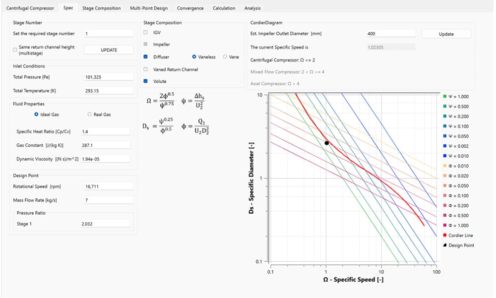
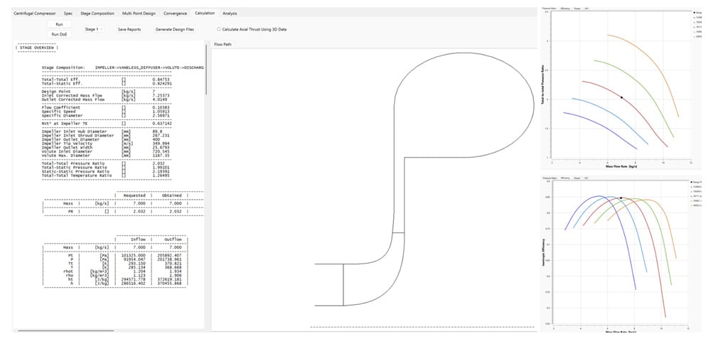
Figure 2: TURBOdesign Pre instantaneously generates the meanline shape and performance maps for the compressor stage from the key input parameters
This outline is then transferred to TURBOdesign1 where, rather than guessing blade profiles, the impeller is generated using 3D Inverse Design. In this formulation, the blade geometry is computed directly from fluid-dynamic input distributions:
- Spanwise circulation (rVtheta*) Controls specific work and work distribution from hub to shroud.
- Streamwise blade loading (
 ): Governs the pressure difference between the blade pressure side and suction side, directly dictating adverse pressure gradients and secondary flow migration.
How does automated volute matching reduce design variables?
Conventionally, adding volute parameters (cross-sectional area distribution, casing shape, radial/tangential offsets) exponentially bloats the Design of Experiments (DoE). In this workflow, TURBOdesign Volute eliminates these extra free variables. It takes the mixed-out diffuser exit flow properties (V_r, V_θ, static pressure, and temperature) predicted by the inverse design solver and automatically computes the optimal matched volute geometry. As the rotor and diffuser shapes evolve during optimization, the volute updates automatically to preserve stage matching.
What is Physics-Enhanced Machine Learning (PEML)?
Geometry driven machine learning often fails in turbomachinery because random geometric permutations produce unphysical shapes, severe blade separation, or unfeasible pressure ratios. The ‘AI’ within the system has to infer the flow physics from the simulation results.
The real solution is Physics Enhanced Machine Learning (PEML). This is a system developed by Advanced Design Technology (ADT) where the inputs to the problem are controls on the physics of the flow in the blade passage. The outputs are blade shapes. Thus what we want from the design (flow, performance, speed etc) is a controlled value, the solutions just attempt to answer that requirement in different ways. The system can’t hallucinate because the process of getting outputs from the input is physics-bound.
Using 3D Inverse Design also means that the parameterization of the design space is incredibly efficient. In this complete compressor stage we need just 9 physics-based input design parameters:
- 4 Blade loading control inputs: Leading-edge (LE) loading and loading slope at the hub and shroud (governing incidence and rate of diffusion).
- 4 Meridional shape inputs: Impeller axial length, inlet diameter, diffuser length and exit tip width
- Wrap Angle: Constrained between -4 to +2 degrees for mechanical integrity and sweep control.
Because every candidate impeller generated via 3D inverse design is mathematically guaranteed to deliver the required specific work (controlled by rVtheta*), all designs meet the design-point pressure ratio requirement. The optimizer needs only to search among viable aerodynamic geometries.
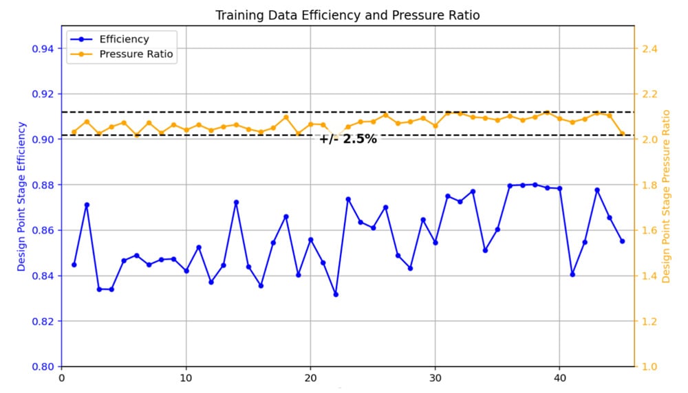
Figure 3: All designs in the training dataset meet the design-point pressure ratio requirement.
Automated CAE Integration & Training Data
The TURBOdesign1 workflow integrates directly with standard commercial CFD solvers (such as Ansys CFX, Siemens Simcenter STAR-CCM+, and Cadence Fine Turbo):
- Simulation Type: Multi-domain, multi-frame of reference (frozen rotor / stage interface), full 3D stage CFD (impeller + diffuser + volute).
- Turbulence Modeling: k-omega SST.
- Operating Points Evaluated per Case at 16711 rpm:
- OP1 (Design Point): 7 kg/s
- OP2 (Near-Surge / Low Flow): 5.95 kg/s
- OP3 (Near-Choke / Low PR): Static back-pressure of 103 kPa
A DoE of 45 candidate designs was executed across all 3 operating points, at 3 operating points this requires 3x45=135 CFD runs, completing in 77 total wall-clock hours on 36 cores.
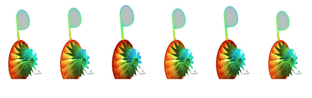
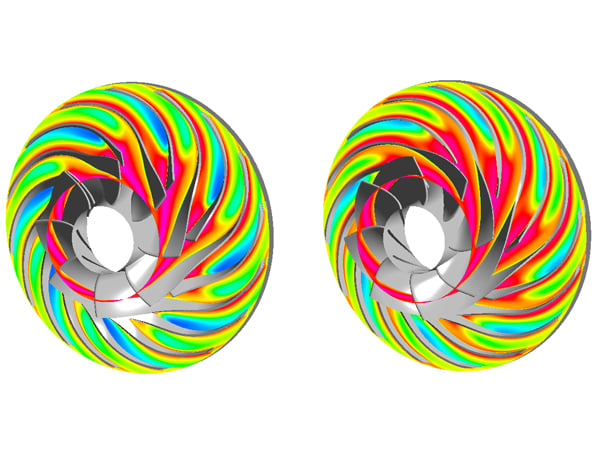
Figure 4: Sample of rotor, diffuser and volute geometry variation during the creation of the CFD training data
Multi-Objective Optimization Targets
The surrogate machine learning model is then constructed from the training data and a 3D Pareto front targeting 3 objectives emerges:
1. Maximize stage efficiency at design flow.
2. Maximize stage pressure ratio at low flow to suppress stall inception and extend the surge margin.
3. Maximize mass flow rate at high flow to broaden the choke margin.
Interrogating the Pareto Front & Selecting Candidates
By projecting the multi-dimensional surrogate model across design parameters, aerodynamic trade-offs are instantly seen. The figure below shows how the 3 objectives pay off against each other. Although it is worth remembering that as this is the Pareto front no candidate selected from this cloud of points can be dominated by any other design in the design space. It is just that one design is ‘better’ in one objective than the others at the other 2 objective values.
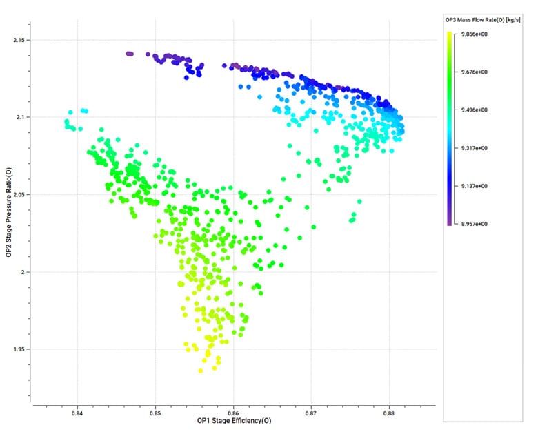
Fig 5: The surrogate model Pareto front created from the training data, showing the 3 optimizer objectives
Two Pareto-optimal candidates were selected for 3D CFD verification:
- Candidate 1 ("Peak Efficiency"): Focused on maximizing aerodynamic recovery and design-point stage efficiency.
- Candidate 2 ("Choke Margin"): Focused on pushing the compressor choke boundary further right without sacrificing baseline stability.
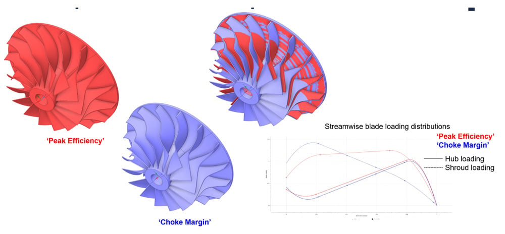
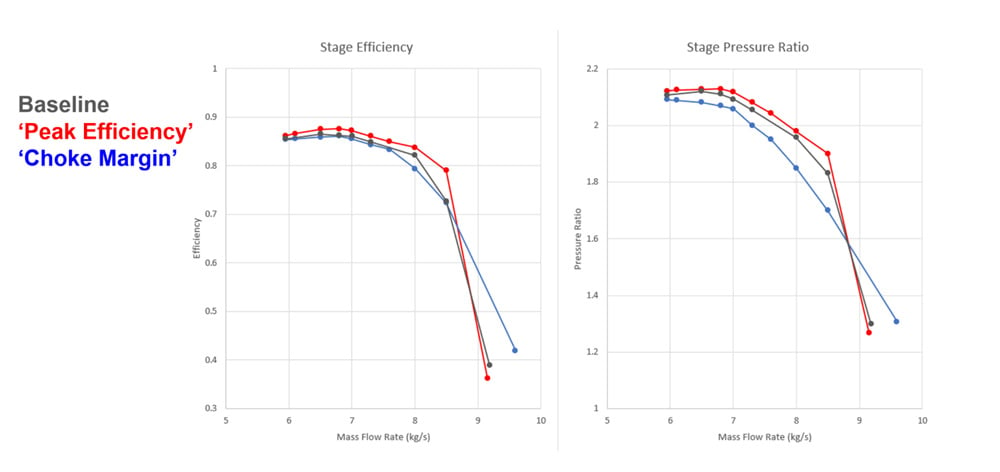
Fig 6: Geometry and discovered performance of 2 Pareto optimal designs
What results did the optimized compressor stage achieve?
Full-stage, multi-point 3D CFD simulations were conducted on the selected designs to validate the surrogate model's predictions. The agreement was exceptionally tight:
Key Takeaways
- Candidate 1 delivered a +1.1% absolute increase in stage efficiency while maintaining or slightly improving surge-side pressure ratio capability.
- Candidate 2 pushed the stage choke boundary from 9.18 kg/s out to 9.70 kg/s +5.7% expansion in operating flow capacity), providing a significantly wider operating envelope for fluctuating industrial plant loads.
- Surrogate Model Accuracy: Across all points, the surrogate model prediction error was under 0.25% for design point efficiency and virtually zero on pressure ratio, proving that physics-based parameter bounds prevent the machine learning model from hallucinating unphysical performance.
Conclusion
Compressor aerodynamic design no longer requires choosing between oversimplified isolated component optimization and intractable weeks-long computing campaigns.
By coupling 3D Inverse Design with Physics-Enhanced Machine Learning, engineers reduce the dimensional complexity of the problem, automate volute aerodynamic matching, and guarantee that every generated DoE point is physically meaningful. This methodology cuts total computational expense by an order of magnitude and delivers proven, manufacturable efficiency gains across the entire compressor operating map.
This Physics Enhanced Machine Learning system, available right now, can be applied to compressor stages of all types. And to all other types of turbomachinery: pumps, fans, turbines, blowers. In any flow regime or working fluid.
If you want to see how Physics-Enhanced Machine Learning can accelerate your design cycles then get in touch with our team at sales@adtechnology.com or explore the TURBOdesign Suite features on our website.
Book a LIVE demo on the design of a turbomachinery application of your choice.
Our demo is tailored to your specific application and design challenges


Share This Post