Transonic centrifugal compressors with pressure ratios higher than 5:1 are commonly used in marine diesel turbocharger applications as well as in helicopter engines and other gas turbine applications. These compressors, which tend to operate at relatively high tip speeds of 500-600 m/s, need to provide high efficiency over a broad range of operation as well as being reliable structurally.
In recent years there has been a number of studies of the flow field in these types of impellers by using detailed LDV
and/or L2F (Laser-Two-Focus) measurements, see Eisenlohr, et al. (2002) and Ibaraki et al (2003). Such measurements coupled with recent numerical analysis of the flow through these impellers, see Marconcini et al (2008) and Ibaraki, et al. (2008) have helped to explain the nature of the flow inside these impellers. The flow seems to be dominated by strong 3D interaction of inducer shock with tip clearance flow, secondary flows and possible incidence effects on the splitter blade leading edge.
Despite the complexity of the flow field, these impellers are generally designed by using straight filaments, partly due to requirements for flank milling of impellers and partly due to perceived possible structural integrity issues with 3D blade profiles. However, in recent years many centrifugal compressor manufacturers, especially in turbocharger and helicopter engine applications, have been changing their manufacturing system to point milling and have found that the extra cost of point milling can be only 10-20% more than an equivalent flank milling process, Thiele ( 2000). Furthermore, it has become increasingly clear that further performance improvement is only possible by using 3D blade profiles, especially for the impeller, see Zangeneh et al ( 2010).
Robust and reliable design of impellers with 3D geometry also poses difficulties for designers. The ‘direct’ design
approach based on iterative modification of the blade shape results in a time consuming design process, especially if
various multi-objective requirements of the impeller design for turbocharger applications are to be met. These difficulties are compounded for impellers with splitter blades, which are commonly used in turbocharger applications.
In conventional design practice, it is customary to use the same blade angle on the splitter blade as on the main blades
with splitter camber line being placed at mid-pitch between the two main blades. There is, however, considerable evidence that this practice leads to poor performance of the splitter blade as a result of the mis-match between the splitter leading edge blade angle and the local flow angles.
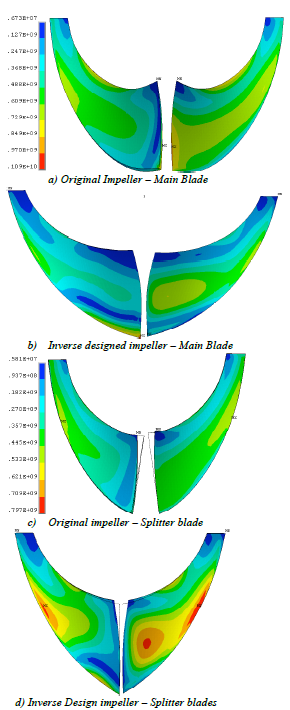
Fig. 1. Comparison of Von Mises stresses in Original SRV2 and inverse design impeller – Units are in Pa.
In recent years, there have been some attempts by designers to modify the splitter leading edge slightly to improve the
matching of the splitter to the local flow. An example of this is the work of Drtina et al (1993), who showed that by modifying the pitchwise location of the leading edge of a splitter blade they could improve the pressure recovery of a vaned diffuser. However, in the design of 3D blades it is rather difficult to arrive at an optimum pitchwise distribution of the splitter across the span. An alternative approach for the design of centrifugal impellers with 3D geometry is to use a 3D inverse design method such as TURBOdesign1(2009).
In this inverse design method, the blade geometry is computed for a specified distribution of blade loading ( ∂rV / ∂m θ ), which is the meridional derivative of the tangentially mean swirl velocity and is directly related to the blade bound circulation 2πrVθ . In this method, in addition to the blade loading the normal thickness distribution is specified. The basic theory behind this approach is also presented in Zangeneh (1991) and its extension to design of blades with splitters is presented in Zangeneh (1998). The inverse design method TURBOdesign1 allows the designer to design the blade geometry on the full and splitter blades subject to a specified distribution of blade loading and therefore automatically optimizes the pitchwise location of the splitter blade across the span.
The method has already been applied to the design of industrial centrifugal compressor impellers, where simple design guide-lines have been developed for suppression of secondary flows and the resulting jet/wake flow effects at the
impeller exit (see Zangeneh et al, 1998 and 1999). This method has also been applied to the design of compact high performance vaned diffusers for centrifugal compressors (see Zangeneh et al, 2002) and industrial compressors with splitters, see Zangeneh et al (2004) and Schleer et al (2004) and turbochargers for heavy-duty diesel applications, see Zangeneh et al (2010).
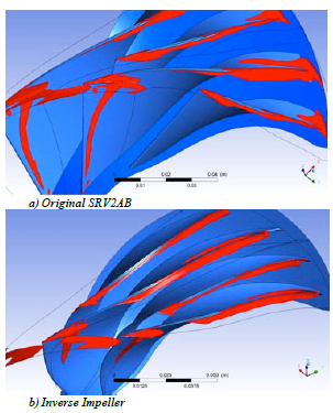
Fig. 2. Comparison of Iso Surfaces of Absolute Helicity
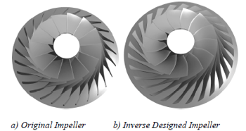
In this paper, this inverse design approach is applied to the redesign of a 586 m/s tip speed impeller which has been the
subject of extensive detailed experimental measurements and numerical analysis at DLR, see Krain and Hofmann (1998),
Eisenloher et al (2002) and Krain et al (2007).

Book a LIVE demo on the design of a turbomachinery application of your choice.
Our demo is tailored to your specific application and design challenges


Share This Post