In the second blog introducing the new TURBOdesign Suite 2020 we are going to show how the new platform enables designers to rapidly evaluate designs.
Fig.1 relates to the design of a centrifugal pump impeller. The meridional shape and blade loading came directly from TURBOdesign Pre (the initial sizing code in TURBOdesign Suite). TURBOdesign Pre already sets an initial blade loading based on pump specific speed which is set up to maximise impeller efficiency. This is a fore-loaded distribution on the shroud and aft-loaded on the hub which results in reduction of secondary flows and hence improve stage efficiency. However, as you can see from the static pressure plot, shown on the right-hand side in Fig.1, the static pressure on the shroud streamline (shown in blue) is very low at 10% meridional chord and this could impact cavitation performance.
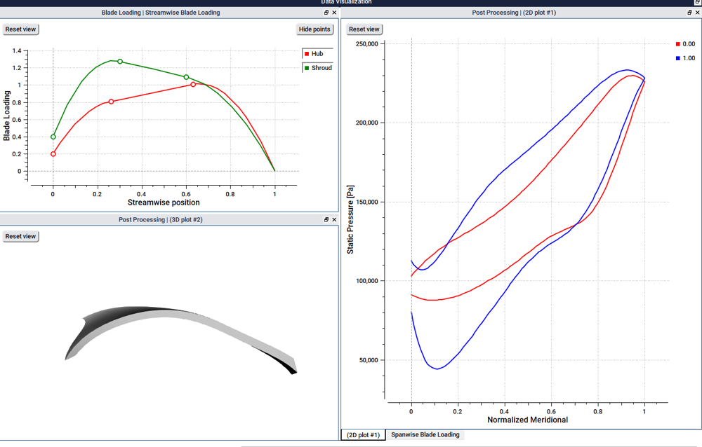
Fig. 1. Example loading used for a centrifugal pump Impeller design and resulting predicted static pressure and 3D impeller Geometry
In Fig. 2, we show the new loading distribution which was changed interactively by moving control points on the shroud to aft-load the shroud. The effect of this change on resulting blade shape and the surface static pressure are shown instantly. The solid blue line is the static pressure on the shroud of the new design and the dashed blue line is the first design. It is possible to see the effect on the static pressure immediately and since the blade static pressure predicted by TURBOdesign matches well with CFD (see our previous blog, on the overview and key new features of TURBOdesign Suite 2020) then this means the increase in minimum pressure on the shroud should result in improvement in suction performance.
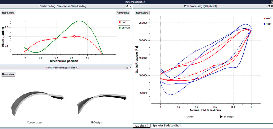
Fig. 2. Impact of changes of blade loading at the shroud on the static pressure and 3D geometry
In Fig. 3, the two 3D geometries are overlaid to show the effect of the blade loading changes on the 3D blade shape. On the right-hand side, you can see comparison of blade angle at the hub and shroud of the original design versus the new design. There is clearly a very large blade angle change, at the shroud but also at the hub, even though the loading was only changed at the shroud in this case and the same blade loading was used at the hub. The 3D nature of the flow field means the geometry is automatically changed by the 3D inverse design method to reflect the impact of the changed in loading on the shroud over the whole impeller geometry. The power of inverse design process is that by using flow related design parameters (blade loading) difficult design problems can be solved quickly without the need for large number of iterations.
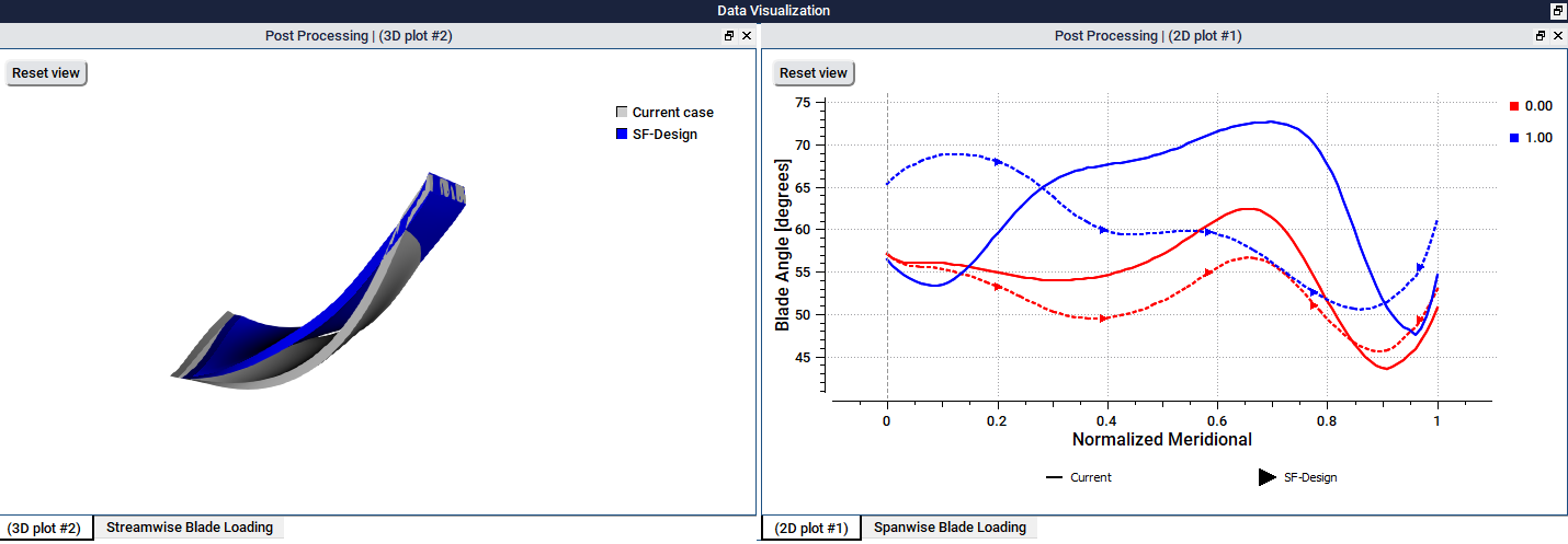
Fig. 3. Impact of the design changes on 3D blade shape and blade angles
In this webinar we will provide further details of the new system and also a number of applications related to turbocharger turbine and mixed flow compressor with tandem diffuser.
Book a LIVE demo on the design of a turbomachinery application of your choice.
Our demo is tailored to your specific application and design challenges


Share This Post