The first step in the design of any turbine is to identify the required specific speed regime of the turbine. This will dictate the meridional shape and hence the general flow direction through the machine. For example, a low specific speed turbine is likely to be a radial inflow type, whereas a high specific speed one is likely to be of mixed or axial flow type.
From the required specific speed, we can identify the main flow phenomena and loss mechanisms dominant in that particular range. For example, as the NsDs turbine chart in Figure 1 shows, leakage and secondary flow effects are more dominant in the lower ranges, whereas shocks and profile losses take priority in the higher ranges.
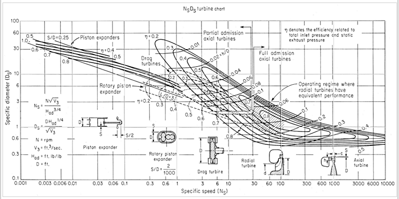
Figure 1: NsDs turbine chart [1]
In fact, with inverse design, it is possible to come up with a set of optimal design guidelines based on these fluid dynamic considerations of reducing the dominant flow losses for your turbine. However, when it comes to high-speed turbines, there is usually a trade-off between the aerodynamic and structural aspects of the rotor, and this brings us to our problem statement.
Problem Statement
The design of high-speed low pressure axial turbines, such as those used in aero-engine last stages, is a complex multidisciplinary problem because the higher rotational speed has conflicting effects on the turbine:
- It does bring efficiency benefits and a reduced number of stages and hence the turbine weight and the overall dimensions
- But it increases the average isentropic Mach number which could create shock losses and it also leads to high stresses in the last stage rotor blade
Hence, the design of such turbines has to find the right balance between aerodynamic performance and mechanical integrity. This is why traditional methods often involve multiple iterations between CFD and FEA runs in order to ensure that the appropriate trade-off is achieved, which consumes a lot of computational time and resources. So the question is whether it is possible to come up with a rapid optimization methodology focused at suppressing the dominant loss mechanisms but without adversely impacting the stresses in your axial turbine, and this is what we aim to explore through this work.
Figure 2 shows the specifications and meridional shape of the last stage of a high-speed low-pressure axial turbine which has previously been studied both numerically and experimentally [2]. Interestingly, due to the high rotational speed, the last stage rotor blade was seen to suffer from elevated Mach number levels and stresses. Therefore, in this article based on one of ADT’s technical papers that was presented at the ASME Turbo Expo 2023 [3], the last stage rotor blade is redesigned keeping the stator blade same as before.
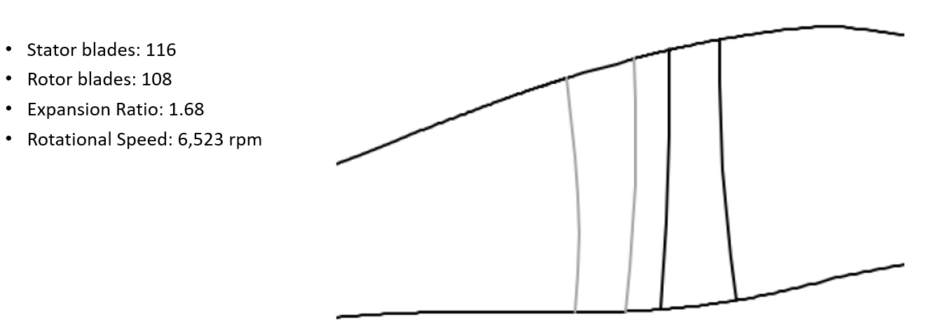
Figure 2: Specifications and meridional shape of the last stage stator and rotor [2]
3D Blade Design of Rotor
Figure 3 presents the setup for the baseline axial turbine rotor in our 3D inverse design software TURBOdesign1, where the meridional design, thickness and the spanwise swirl (rVt*) distribution are extracted from the CFD results of the original turbine and can directly be used as design inputs.
Since the rVt* distribution at the rotor leading edge is the same as that at the stator trailing edge, this automatically ensures a good matching between them. Naturally, there is a drop in rVt* at the trailing edge after work is extracted from the fluid. The default blade loading distribution is mid loaded at the hub and aft loaded at the shroud for this baseline rotor.
Additionally, the inlet axial and radial velocity and temperature profiles are also imposed as boundary conditions, and the rotor is radially stacked at 40% of the axial chord which is close to its centre of mass and helps to balance the centrifugal force. These inputs result in 3D geometry of the rotor blade with a smooth Mach number distribution over the entire surface.
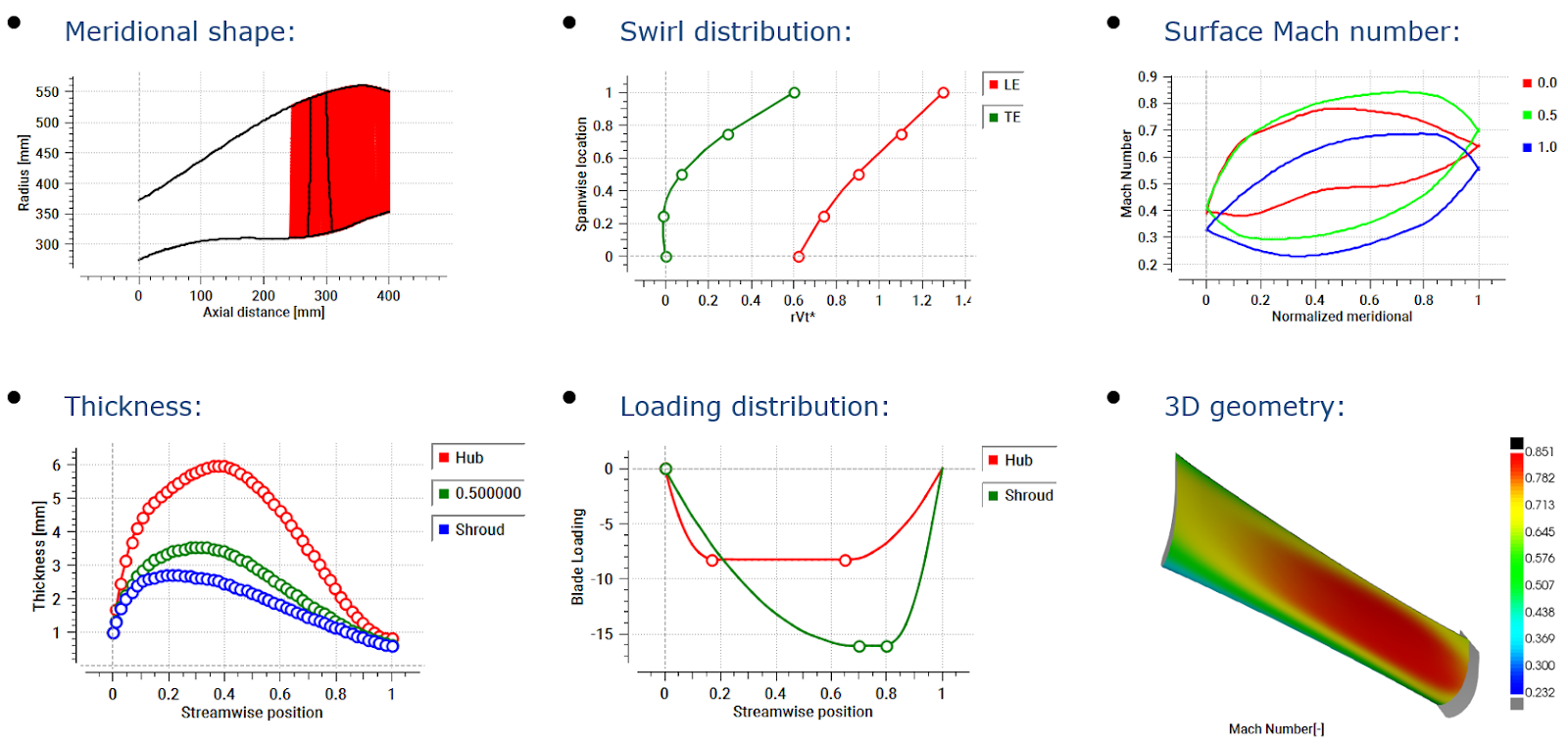
Figure 3: 3D blade design of axial turbine rotor in TURBOdesign1
Baseline CFD Analysis
Once the baseline rotor is ready, a CFD analysis is run with the original stator to check the actual stage performance. As Figure 4 shows, ANSYS TurboGrid is used for the fully structured grids of the rotor, stator and the downstream diffuser passages and CFX for the flow analysis. Here are the different CFD settings where the inlet and outlet boundary conditions are taken from previous multi-stage simulations of the original turbine:
- Inlet BC: Spanwise profiles of P01, T01 and flow direction
- Outlet BC: Spanwise profile of P2
- Stator-rotor interface: Stage (mixing plane)
- Rotor-diffuser interface: Frozen rotor
- Turbulence model: K-omega SST
- Average blade y+: < 1
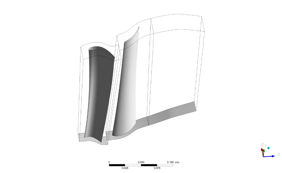
Figure 4: Axial turbine stage CFD setup
When stage CFD runs are performed, it is found that the stage pressure ratio is 1.68 and the total-to-total isentropic efficiency is more than 94% at the design point, as shown in Figure 5.
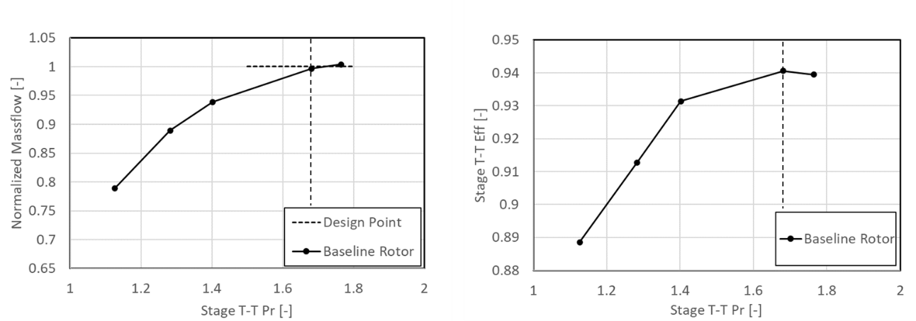
Figure 5: Stage normalized mass flow (left) and total-to-total isentropic efficiency (right) with the baseline rotor
Figure 6 presents the rotor surface isentropic Mach number from CFD, and here we can see that from midspan up to the shroud, the peak values on the suction surface are above 1, and this could potentially result in shock losses and is something that needs to be addressed.
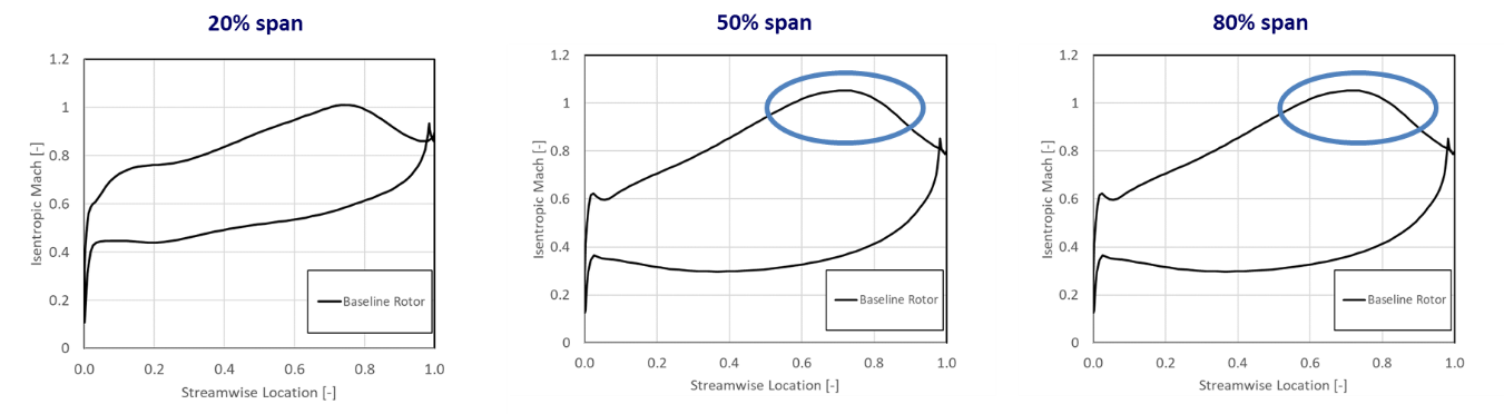
Figure 6: Baseline rotor blade surface isentropic Mach number
Baseline FEA Analysis
Some blade-only FEA is also performed to evaluate the mechanical integrity of the baseline rotor, and here are the details of the stress analysis which was done using ANSYS Static Structural:
- Mesh size: 1.49 M
- Fixed support: Blade root
- Rotational speed: 6,523 RPM
- Material: Titanium alloy
- Young’s Modulus: 104 GPa
- Poisson’s Ratio: 0.31
- Tensile Yield Strength: 600 MPa @ 400°C
From the von-Mises stress contours in Figure 7, it is clear that there is a high stress concentration at the blade trailing edge near the hub.
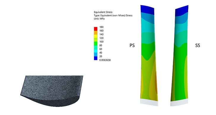
Figure 7: Baseline rotor FEA mesh detail (left) and blade stress contour (right)
Therefore, it is evident that both aerodynamic and mechanical aspects of the baseline rotor need to be addressed. In the second part of this article, we introduce a rapid optimization methodology combined with inverse design to enhance the baseline rotor. This approach enables us to simultaneously improve both the aerodynamic performance and structural integrity of the rotor using our turbine design software.
Software Demo - Design of Axial Turbine Rotor with 3D Inverse Design
References
[1] O. E. Balje, “TURBOMACHINES : A Guide to Design, Selection, and Theory”, A Wiley-Interscience Publication, (1981)
[2] Giovannini, M., Rubechini, F., Marconcini, M., Arnone, A., Bertini, F., 2016, “Analysis of a LPT Rotor Blade for a Geared Engine: Part I — Aero-Mechanical Design and Validation,” ASME Turbo Expo 2016: Turbomachinery Technical Conference and Exposition, GT2016-57746, V02BT38A053; 12 pages, June 13–17, 2016, Seoul, South Korea
[3] Zhang, L., Zangeneh, M., “Multidisciplinary Optimization of a High-speed Low Pressure Turbine Rotor Using 3D Inverse Design Method”, Proceedings of ASME Turbo Expo 2023, GT2023-102007, June 26-30, 2023, Boston, Massachusetts, USA

Book a LIVE demo on the design of a turbomachinery application of your choice.
Our demo is tailored to your specific application and design challenges


Share This Post