The first step in the design of any turbine is to identify the required specific speed regime of the turbine. This will dictate the meridional shape and hence the general flow direction through the machine. For example, a low specific speed turbine is likely to be a radial inflow type, whereas a high specific speed one is likely to be of mixed or axial flow type.
From the required specific speed, we can identify the main flow phenomena and loss mechanisms dominant in that particular range. For example, as the NsDs turbine chart in Figure 1 shows, leakage and secondary flow effects are more dominant in the lower ranges, whereas shocks and profile losses take priority in the higher ranges.
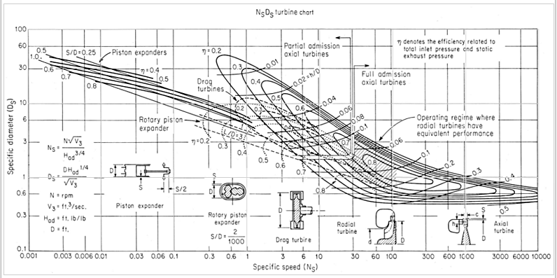
Figure 1: NsDs turbine chart [1]
In fact, with inverse design, it is possible to come up with a set of optimal design guidelines based on these fluid dynamic considerations of reducing the dominant flow losses for your turbine. However, when it comes to high-speed turbines, there is usually a trade-off between the aerodynamic and structural aspects of the rotor, and this brings us to our problem statement.
Problem Statement
The design of high-speed radial turbines, such as those used in turbochargers, is a complex multidisciplinary problem with conflicting requirements of extracting efficiency and maintaining acceptable rotor stress levels. Geometry modifications typically used in the industry such as radial filament are structurally safe, but can lead to a considerable compromise in the rotor efficiency. Due to this trade-off, the conventional design methodology is to perform a large number of CFD/FEA runs for the design matrix (DOE), and subsequent response surface optimization. Therefore, the question is whether it is possible to come up with a rapid optimization methodology focused at suppressing the dominant losses but without adversely impacting the stresses in your radial inflow turbine, and this is what we aim to explore through this work.
Meanline Design of Radial Inflow Turbine Stage
- Expansion Ratio: 2.2
- Rotational Speed: 70,000 rpm
- Flow Rate: 0.31 kg/s
Using the meanline code TURBOdesign Pre, it is very easy to enter the given specs and verify that it sits in the high efficiency region of the specific speed diagram, and then it quickly generates the meridional shape of the radial inflow turbine stage in less than a second. As Figure 2 shows, it also provides a detailed report including the estimated stage performance and some important dimensions, as well as the required rVt* for the rotor and the nozzle. These rVt* values are equivalent to work coefficients and will be used for the 3D inverse design of these components in the next section.
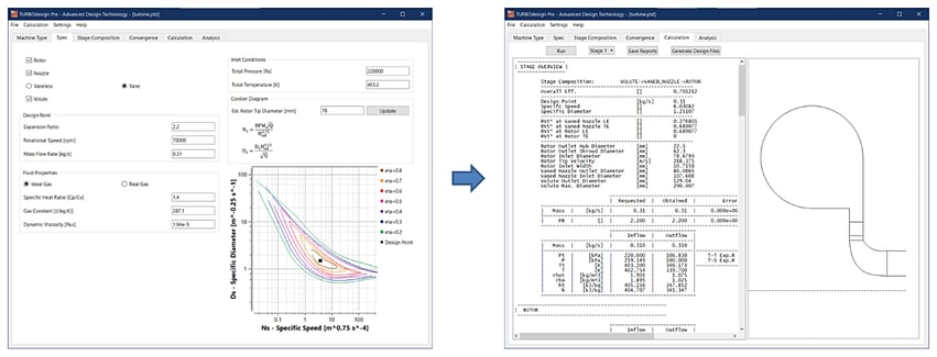
Figure 2: Meanline design of radial inflow turbine stage in TURBOdesign Pre
Software Demo - Meanline Design of Radial Inflow Turbine Stage in TURBOdesign Pre
3D Blade Design of Nozzle and Rotor
Figure 3 presents the setup for the baseline radial inflow turbine stage in our 3D inverse design software TURBOdesign1, where the meridional shape and other default settings come from the meanline code. Otherwise, it is also possible to import your own custom thickness profiles. The spanwise work distribution for each component is free vortex, and so it has a constant value from hub to shroud. It is worth noting that the rVt* at the rotor leading edge is kept the same as the nozzle trailing edge, and this automatically ensures a good matching between them. The loading distribution is aftloaded for the nozzle and for this baseline rotor, it is fore-loaded at the hub and aftloaded at the shroud. These inputs result in 3D geometries of the two components in their correct locations as shown alongside.
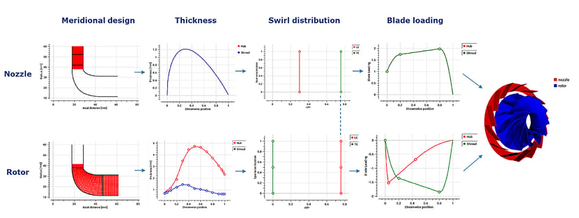
Figure 3: 3D blade design of rotor and nozzle vane in TURBOdesign1
Software Demo - Design of Rotor and Nozzle of a Radial Inflow Turbine with 3D Inverse Design
Volute Design
The meanline code TURBOdesign Pre also generates a volute report, and this information is used by TURBOdesign Volute to design the volute for the radial inflow turbine. As shown in Figure 4, along with the main dimensions, it is also possible to define the cross-section shapes at the entry, duct and inlet which are selected as asymmetric elliptic external in this case. The most important input is the boundary conditions at the volute outlet, i.e., the radial and tangential velocity components and the total pressure and temperature, because then TURBOdesign Volute runs a 2D inverse design code to generate the optimum cross-section area distribution for the given flow conditions at the inlet of the vaned nozzle.

Figure 4: Volute design for a radial inflow turbine using TURBOdesign Volute
Software Demo - Design of Volute of a Radial Inflow Turbine with TURBOdesign Volute
Baseline CFD Analysis
Once all the components of the radial inflow turbine stage are ready, a stage CFD analysis is performed to check the actual performance. As Figure 5 shows, ANSYS TurboGrid is used for the fully structured grids of the rotor and the vaned nozzle passages, ANSYS Mesh for the hybrid mesh of the volute, and CFX for the flow analysis. Here are the different CFD settings where the boundary conditions are chosen to match the inlet and outlet conditions in the TURBOdesign Pre case:
- P01, T01 = 2.2 bar, 403.2 K
- P2 = 1 bar
- Rotor-stator interface = stage (mixing plane)
- Turbulence model = k-omega SST
- Total mesh size ≈ 2.3 M
- Average blade y+ ≈ 5
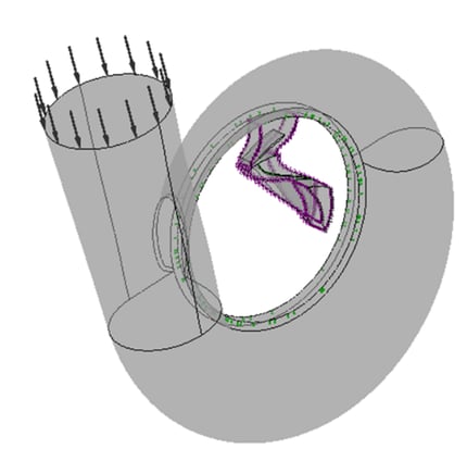
Figure 5: Radial inflow turbine stage CFD setup
Figure 6 presents some results from the baseline stage CFD, and clearly the rotor work coefficient or rVt* that was specified in TD1 is quite close to what we actually get from CFD. The little under-turned region at the trailing edge shroud could be related to the tip leakage effects that are seen only in CFD. Also displayed are velocity vector plots in the blade-to-blade view which confirm good flow behaviour throughout the nozzle and the rotor.
-and-blade-to-blade-velocity-vectors-(right).png?width=752&height=367&name=Baseline-radial-turbine-rotor-work-coefficient-(left)-and-blade-to-blade-velocity-vectors-(right).png)
Figure 6: Baseline radial turbine rotor work coefficient (left) and blade-to-blade velocity vectors (right)
Next, a radial filament modification is applied to the original 3D blade rotor which is the conventional method to minimize the centrifugal bending stress, and then stage CFD runs are repeated with the radial filament rotor. As illustrated in Figure 7, the design mass flow rate is found to be very close to the specified value of 0.31 kg/s with both the rotor designs. However, the radial filament modification results in more than 1 point drop in stage total-static efficiency at the design speed (70,000 RPM).
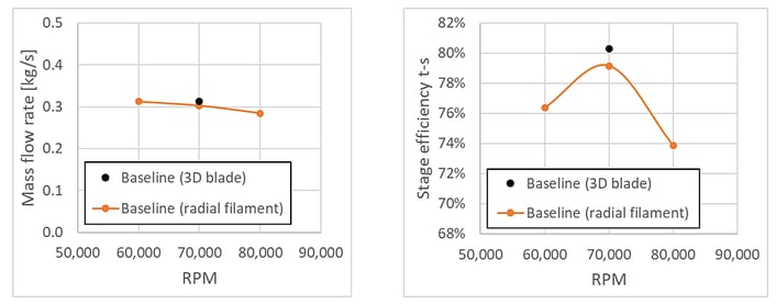
Figure 7: Comparison of stage mass flow rate and total-static efficiency between 3D blade and radial filament rotors
Baseline FEA Analysis
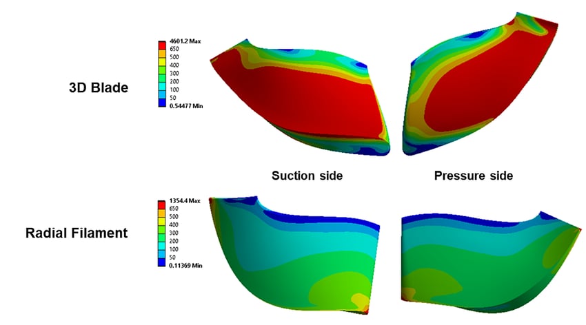
Some blade-only FEA is also performed to assess the mechanical integrity of the two rotor designs at the maximum speed of 120,000 RPM. From Figure 8, it is clear that the Von-Mises stress in the 3D rotor exceeds material yield strength over a significant portion of the blade, whereas the radial filament modification brings down the stresses to well within material limit, thus making the turbine operation quite safe.
Therefore, it is evident that there is a trade-off when it comes to the aerodynamic and mechanical performance of the rotor. In fact, it is possible to strike a balance between these two extremes through the use of automatic optimization and therefore, in the second part of this article, we present a rapid methodology to optimize the baseline 3D rotor to a less 3D blade (not completely radial-filament) and thus obtain the desired trade-off.
References
[1] O. E. Balje, “TURBOMACHINES : A Guide to Design, Selection, and Theory”, A Wiley-Interscience Publication, (1981)

Book a LIVE demo on the design of a turbomachinery application of your choice.
Our demo is tailored to your specific application and design challenges


Share This Post