In the first part of this article on the baseline design of a radial inflow turbine stage, we showed that there is a clear trade-off when it comes to the aerodynamic and mechanical performance of the rotor.
In this second part, we demonstrate the use of Optima feature in TURBOdesign1 to rapidly optimize the baseline 3D rotor to a less 3D blade (not completely radial-filament) and thus obtain the desired trade-off.
Optimization Workflow
Figure 1 displays the workflow used by the automatic optimization, where the blade loading and stacking parameters are used to generate the blade shape in TURBOdesign1, and then the resulting performance parameters are fed into Optima which basically applies MOGA to drive the solution towards the optimum design.
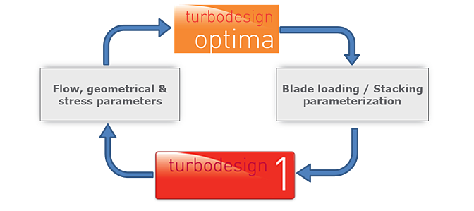
Figure 1: Workflow used in automatic optimization
Optimization Setup
The optimization process starts by specifying the range of variation for the input parameters shown in Figure 2, which are the streamwise loading parameters as well as the trailing edge work coefficient because it has an influence on the blade wrap where the stresses are maximum. Also shown are the constraints where, in addition to the throat and the overall diffusion ratio, some wrap angle and work related user-defined parameters are also constrained:
- UD_Wrap is the wrap angle difference between 15% span and hub at blade trailing edge
- UD_RMSE calculates the root mean square error of all the wrap angle difference between these various locations which would be zero for a perfectly radial-fibred blade
- UD_work is calculated by the volume flow averaged rVtheta variation between the leading and trailing edges, and is related to the turbine power through Euler’s turbomachinery equation
Finally, for the optimization objectives we want to minimize the profile loss and the leaving kinetic energy in order to maximize the efficiency. But at the same time, for keeping the blade stresses in check, we also want to minimize some wrap angle parameters like:
- UD_MaxDeviation is the maximum value of all the wrap angle differences used in the calculation of UD_RMSE
- UD_0.9_MaximumBow is the maximum deviation from linear span at 90% of streamwise location near the trailing edge and would be zero for a perfectly radial-filament blade
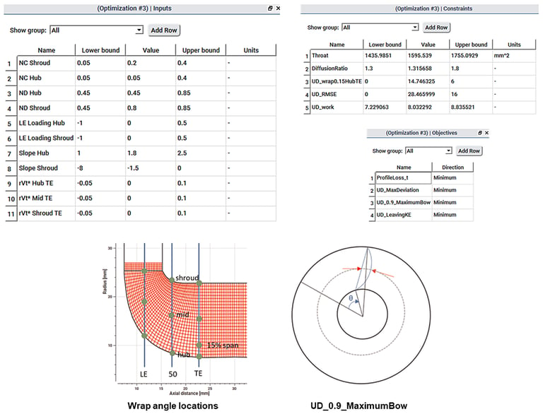
Figure 2: Inputs, constraints and objectives used in automatic optimization
In this way, using these wrap angle parameters we ensure that blade integrity is not compromised in the process of improving its aerodynamic performance. In fact, this methodology was successfully used in one of ADT’s recent technical papers that was presented at the 15th IMechE turbocharging conference [1].
Optimization Results
Once the optimization run is complete, which is very fast and only takes about an hour or so on a single core machine, the design candidates can be seen on a scatter plot between any two objectives, in this case the maximum bow on the X axis and the maximum deviation on the Y axis as shown in Figure 3. Here we have chosen to see only the feasible designs which respect all of our specified constraints, and the position of the baseline 3D rotor relative to the candidates may also be observed.
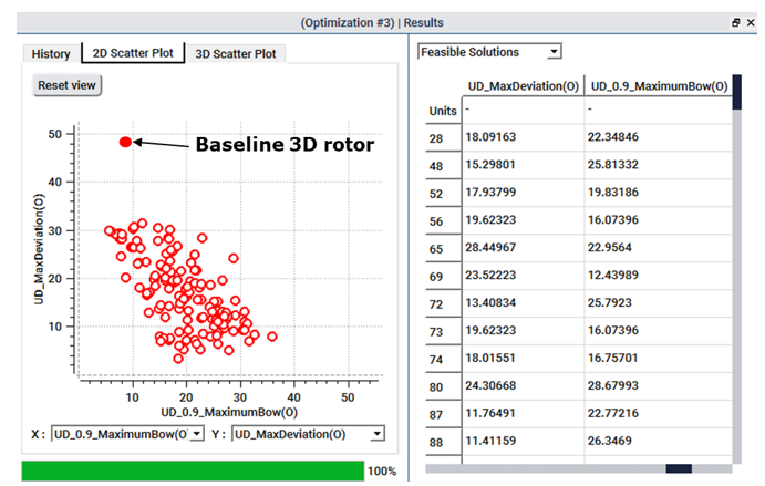
Figure 3: Scatter plot between maximum deviation and maximum bow of feasible designs
Next as Figure 4 shows, we can choose to see the Pareto front of optimum designs from which we can pick and analyse any design of interest. For the present work, we select a design which gives us the lowest combination of maximum bow and maximum deviation and thus brings us as close as possible to a radial filament rotor, and so we use this design for further analysis and for comparison with the baseline rotor.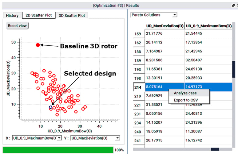
Figure 4: Pareto front of optimum designs with the selected design
Figure 5 reveals what changed as a result of the optimization. For the streamwise blade loading, compared to the baseline rotor, the optimizer increases the aft-loading at the shroud even further, in order to reduce the profile loss. Regarding the spanwise work (rVt*) distribution, the optimizer recommends leaving a slight swirl at the trailing edge for improving the blade wrap in this area. As a result, the optimized rotor clearly looks very different from the baseline rotor. While the baseline 3D rotor had a high lean or wrap at the trailing edge, the optimized design features a much more radial blade which should help cut down the stresses in this area.
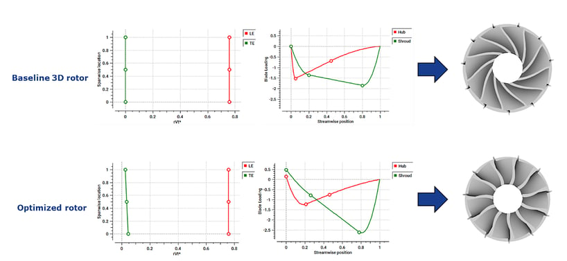
Figure 5: Comparison of spanwise work and blade loading between baseline and optimized rotor
Optimized Rotor Performance
The mechanical performance of the optimized rotor is investigated first. So far as TURBOdesign1 performance parameters are concerned, there is a substantial improvement in the various wrap angle-related parameters, due to which the wrap angle distribution in the optimized rotor is quite close to radial filament near the exducer region as shown in Figure 6.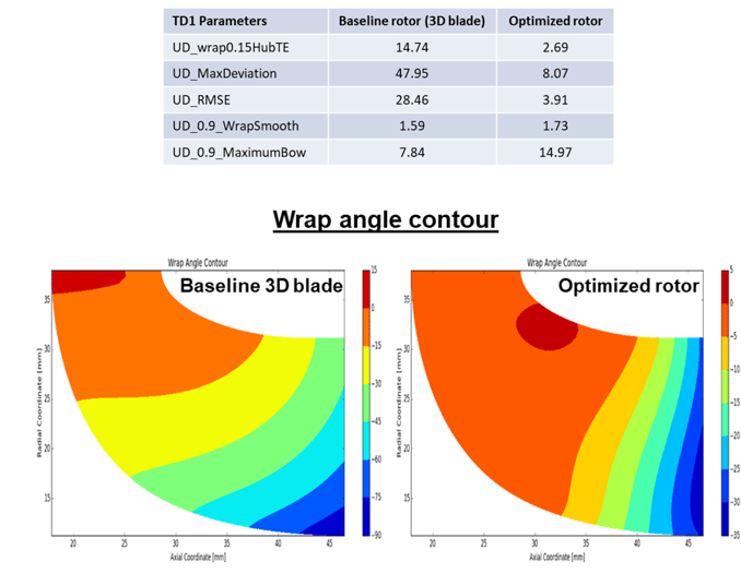
Figure 6: Comparison of wrap angle parameters and contour between baseline and optimized rotor
As illustrated in Figure 7, an FEA analysis provides final confirmation that the peak stress in the optimized rotor is contained well within the yield strength of the material. Although there is a small region of high stress on the pressure side trailing edge, this is mainly caused by a lack of modelling the fillet.
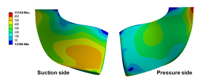
Figure 7: Optimized rotor von-Mises stress contour
Finally, what remains to be verified is the aerodynamic performance. Figure 8 presents the effect on the TURBOdesign1 performance parameters where there is a significant reduction in the total profile loss and the exit kinetic energy as a result of the optimization.
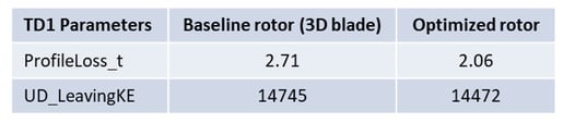 Figure 8: Comparison of aerodynamic objectives between baseline and optimized rotor
Stage CFD is performed with the optimized rotor at three different rotational speeds, keeping the nozzle and the volute the same as the baseline design. The results are displayed in Figure 9, where the peak stage efficiency is preserved very close to the baseline 3D blade levels and is noticeably higher compared to what was obtained with the radial filament rotor. In fact, the benefits are even more enhanced at off-design speeds, reaching up to 3 point improvement at the higher speed. At the same time, the design mass flow rate continues to remain aligned with the specified value of 0.31 kg/s and the close match between the rotor work coefficients (rVt*) of TD1 and CFD is still maintained.
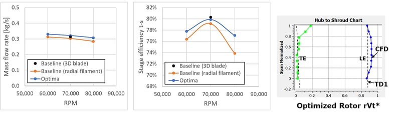
Figure 9: Comparison of stage mass flow rate and total-static efficiency between baseline 3D blade, radial filament and optimized rotors
In this way, the rapid optimization methodology is able to improve the rotor structural integrity substantially without compromising on its aerodynamic performance. The optimization takes less than an hour and only a few CFD and FEA runs are required to achieve and verify the improvements:
- 7 CFD runs (1 3D blade + 3 radial filament + 3 optimized rotor)
- 3 FEA runs (1 3D blade + 1 radial filament + 1 optimized rotor)
Here's the Software Demo of the Automatic Optimization of Radial Inflow Turbine Rotor
Conclusion
High speed radial turbines typically present a trade-off between the aerodynamic and structural aspects of the rotor. Essentially, using inverse design with special user-defined parameters for wrap angle control, it is possible to quickly optimize the rotor and achieve the optimum blade loading for trade-off:
- Shroud should be aft-loaded to reduce profile loss
- Hub should be fore-loaded to suppress secondary flows
- Trailing edge spanwise swirl distribution should be slightly positive to improve wrap and control blade stress in this area
Moreover, this methodology involves very less computational resources in terms of CFD and FEA runs compared to conventional design methods. Our experience has shown that the choice of optimum loading for controlling profile loss or secondary flows has generality and can be applied to other similar applications. For example, we find that for profile loss control, the type of loading that we use for turbines is applicable to all types of turbines, mixed flow and axial and regardless of the turbine speed or size.
References
[1] Zhang, J., Zhang, L., Zangeneh, M., “A 3D inverse design based rapid multi-disciplinary optimization strategy for radial-inflow turbines”, 15th International Conference on Turbochargers and Turbocharging, Institution of Mechanical Engineers, ISBN: 978-1-032-55154-8
Book a LIVE demo on the design of a turbomachinery application of your choice.
Our demo is tailored to your specific application and design challenges


Share This Post