Heat pumps are used to absorb heat from a cold space and transfer it to a warmer one, such as for ambient heating in case of air conditioners. For this, there is a need for a compression device which has traditionally been positive displacement machines for large scale industrial applications.
However, in recent times there has been a shift towards replacing them with centrifugal compressors on account of their potential to significantly increase the energy conversion efficiency. This possibility is now also being explored for smaller scale domestic heat pumps. However, the design of small-scale high speed turbocompressors is a complex multidisciplinary problem:
- The impeller size can be extremely small (< 20 mm), which results in a large tip gap relative to the blade height.
- This also leads to very high operational speeds to generate the necessary pressure ratios, which can have serious implications on the blade stress.
- While fore-loading the impeller at the tip is good to suppress the profile loss and secondary flow, it can significantly increase the tip leakage effects.
This is why conventional methods often involve large numbers of CFD and FEA runs in order to ensure that the appropriate trade-off is achieved, which consumes a lot of computational time and resources. With inverse design, it is possible to come up with a rapid optimization methodology focused at suppressing the dominant losses but without adversely impacting the stresses in the small-scale compressor, and this is what we aim to explore through this project.
Compressor Design Process
The first step in the design of any compressor is to identify the required specific speed regime of the compressor. This will dictate the meridional shape and hence the general flow direction through the compressor. For example, a low specific speed compressor is likely to be a radial or centrifugal type, whereas a high specific speed compressor is likely to be of mixed flow or axial type.
From the required specific speed, we can identify the main flow phenomena and loss mechanisms dominant in that particular range (see Figure 1). For example, leakage and secondary flow effects are more dominant in lower ranges, whereas profile/shock losses and corner separation in diffusers take priority in the higher ranges.

Figure 1: Cordier diagram
From the information above we can use design tools and 3D CFD to investigate our compressor designs, what follows are a set of principal design guidelines based on the fluid dynamics considerations of reducing dominant flow losses for a given compressor.
Meanline Design of Heat Pump Compressor Stage
Below are the specifications that are used to design the small-scale heat pump compressor, which consists of an impeller, a vaneless diffuser and a volute:
- Total pressure ratio: 2.0
- Rotational Speed: 400,000 rpm
- Flow Rate: 0.01 kg/s
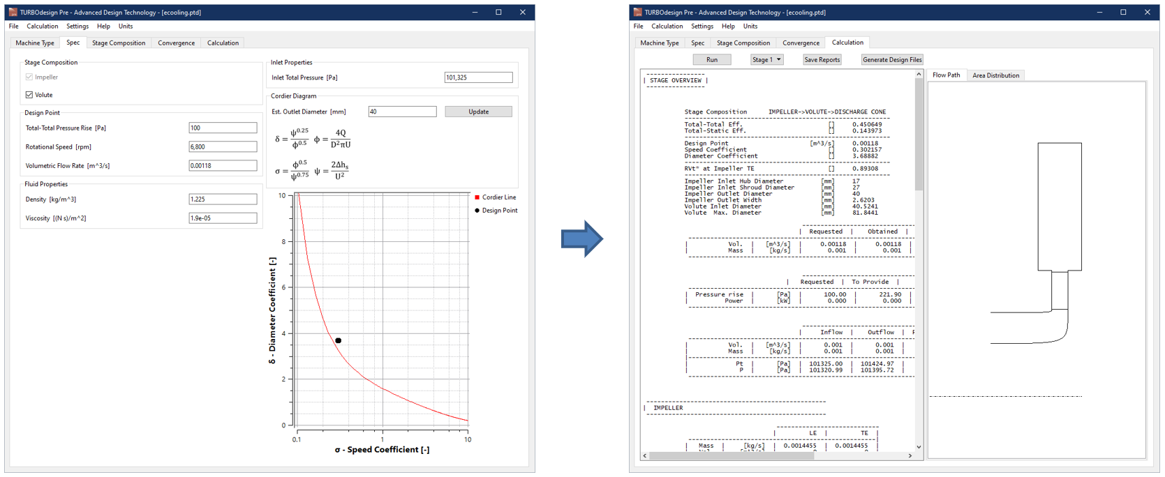
Figure 2: Meanline design of heat pump compressor in TURBOdesign Pre
Software Demo - Meanline Design of a Heat Pump Compressor with TURBOdesign Pre
3D Blade Design of Impeller
Figure 3 presents the setup for the baseline impeller in our 3D inverse design software TURBOdesign1, where the meridional design comes from the meanline code as we saw earlier. Since the smallest manufacturable thickness has been identified as 0.2 mm in the literature [1], a constant thickness of 0.25 mm has been selected in this case. The spanwise work distribution is free vortex, and so it has a constant value from hub to shroud, and for this baseline impeller the streamwise loading is fore-loaded shroud and aft-loaded hub which is well-known to suppress secondary flows in subsonic compressors. It is also worth noting that a high leading-edge loading is used throughout the blade which helps to increase the throat area for maintaining the peak efficiency at design flow conditions, while reducing the blade lean and bow ratio at the same time to keep the blade stresses low.
These inputs result in 3D geometry of the impeller also shown, along with a smooth static pressure distribution throughout the blade surface. Moreover, TURBOdesign1 performance parameters confirm that the diffusion ratio is within the acceptable limit (< 1.8) to prevent a flow separation scenario.
Furthermore, the maximum surface Mach number is well below 1 thus avoiding any transonic effects, and the leading-edge lean angle and bow ratio are sufficiently low, indicating that the baseline impeller is structurally safe.


Figure 3: 3D blade design of heat pump compressor impeller in TURBOdesign1
Baseline CFD Analysis
Once the baseline impeller is ready, a CFD analysis is run to check the actual performance. As Figure 4 shows, ANSYS TurboGrid is used for the fully structured grid of a single passage, and CFX for the flow analysis.
Following are the different CFD settings where the boundary conditions are chosen to match the inlet and outlet conditions in TURBOdesign Pre.
It may be noted that the tip clearance is large relative to blade exit height which is commonly observed in these small-scale compressors.
- P01, T01 = 1 bar, 300 K
- m2 = 0.01 kg/s
- Tip clearance = 0.1 mm (10% of blade exit width)
- Rotor-stator interface = frozen-rotor
- Turbulence model = k-omega SST
- Total mesh size ≈ 1.6 M
- Average blade y+ ≈ 0.7

Figure 4: Baseline heat pump compressor impeller CFD setup
In fact, the CAE integration feature is used which provides a direct link between blade designs in TURBOdesign1 and their CFD analysis on commercial software.
As Figure 5 shows, all that is needed is to add a CFD connection and select the design that needs to be simulated, after which there is an option to choose between ANSYS CFX and STAR-CCM+, and then provide some other CFD settings such as the wall y+ value, turbulence model and number of iterations.
It is also possible to run multiple points with different flow rates around the design point, for example in this case extra runs are performed at 90% and 110% of the design flow rate to verify the throat area. Once the CFD runs kick off, the mesh is automatically created in TurboGrid and then the CFX solver starts running. When the runs are complete, it is found that the peak efficiency happens at the design flow, meaning that the impeller throat is correctly sized for the design condition.

Figure 5: Baseline heat pump compressor pressure ratio and efficiency curves
Figure 6 reports some more results from the baseline CFD at design point, and here we have these velocity vector plots in the blade-to-blade view which are showing the influence of the large relative tip gap even at 80% of the blade span. However, the flow is otherwise well-behaved inside the impeller.

Figure 6: Baseline heat pump compressor blade-to-blade vector plots
In another article, we demonstrate the use of Optima feature in TURBOdesign1 to automatically optimize the baseline impeller and enhance its aerodynamic performance while guaranteeing structural integrity at the same time.
References
[1] Javed, A., Arpagaus, C., Bertsch, S., Schiffmann, J. (2016) Small-scale turbocompressors for wide-range operation with large tip-clearances for a two-stage heat pump concept Int J Refrig, 69, pp. 285-302

Book a LIVE demo on the design of a turbomachinery application of your choice.
Our demo is tailored to your specific application and design challenges


Share This Post