Across the specific speed range, compressors are subject to various flow phenomena and loss mechanisms which are dominant in that particular range. For example, leakage and secondary flow effects are more dominant in lower ranges, whereas profile/shock losses and corner separation in diffusers take priority in the higher ranges. In this article, we focus on corner separation and how to come up with a set of optimal design guidelines to control this particular loss mechanism in a compressor.
Compressor Radial Vaned Diffuser
This was a collaboration between ADT, ETH, Sulzer Turbo and ABB Turbo where the baseline compressor was tested with a vaned diffuser that was then redesigned. The baseline vaned diffuser had prismatic blades, and a cross section of the ETH test facility is shown in Figure 1. The objectives of this study were:
- To re-design the geometry of an existing vane diffuser to improve pressure recovery especially at lower than design flow conditions.
- To develop design guide lines for diffusers based on this approach.
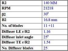
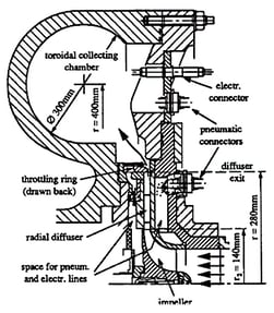
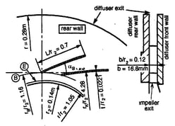
Figure 1: Cross-section of ETH test facility and conventional diffuser geometry
Vaned Diffuser Design
As Figure 2 shows, one of the aspects of this diffuser was that the detailed flow, based on stage CFD, revealed a very big corner separation on the pressure surface near the hub. So the aim was to reduce this corner separation and to make the diffuser more compact. Corner separation is a complex phenomenon as there is also a very strong positive pressure gradient on the pressure surface. When low momentum or low stagnation pressure fluids accumulate at the endwall and then undergo this positive pressure gradient, it results in a huge corner separation.
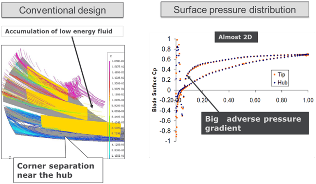
Figure 2: Corner separation phenomenon in vaned diffuser
Main Input Parameters
The following steps were performed for redesigning the diffuser, as shown in Figure 3:
- In order to make the diffuser more compact, the radial extent of the diffuser was reduced by almost one-third from a radius ratio of 1.54 to 1.4.
- The solidity of the diffuser was lowered considerably from 25 blades to 19 blades in order to check if it was still possible to achieve the same level of pressure recovery as the standard diffuser.
- In terms of blade loading, the same type of loading was used which has been found to be very effective in pumps, which are fore-loaded at the hub and aft-loaded at the shroud. A slight negative loading or negative incidence is used on the leading edge to match the standard diffuser's choke margin.
- In order to match the impeller outlet velocity profile at the diffuser inlet, a linear variation of radial velocity is imposed from hub to shroud, whereas the tangential velocity is kept almost uniform.
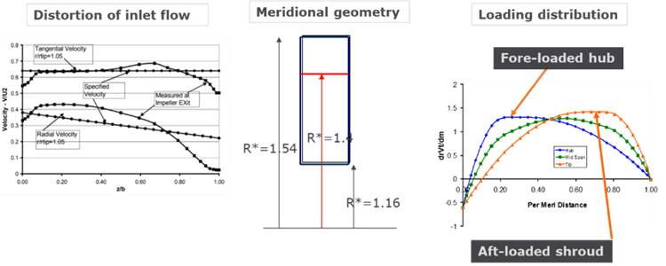
Figure 3: Main input parameters for diffuser redesign
Inverse Design Result
The resulting diffuser blade shape is three-dimensional as shown in Figure 4, and it can be observed that the corner separation has been removed. This is because the applied blade loading produces the following effects:
- It creates strong spanwise secondary flows that move the low-momentum fluid away from the endwall.
- It reduces the amount of positive pressure gradient.
Therefore, a combination of the two helps to eliminate the corner separation.
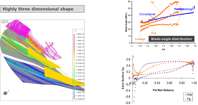 Figure 4: Corner separation elimination in redesigned vaned diffuser
Experimental Validation
Figure 5 presents the measurements performed at the ETH facility first on the original impeller and the original diffuser (orange lines) and then on the original impeller and the new diffuser (blue lines). At the design point, the same level of pressure recovery is achieved even with much lower solidity in the vaned diffuser designed by inverse design. At lower-than-design flow conditions, there is slightly more pressure recovery and slightly less at higher-than-design flow. This trend is respected all the way across the map. Also shown alongside is the detailed flow field at the exit of the diffuser, which shows the blockage distribution at points C, best point (BP) and A. Here, a value of 1 is equivalent to inviscid flow or zero blockage, and a higher value indicates more circumferential non-uniformity at the exit of the vaned diffuser. Clearly, at all operating points, the inverse design shows a much more uniform exit flow compared to the baseline.
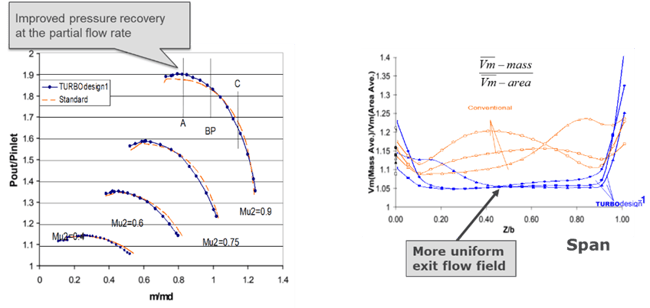
Figure 5: Comparison of measured stage pressure ratio (left) and blockage distribution (right)
Related Article: Optimum Blade Loading for Secondary Flow Reduction in Impellers with Splitters
Book a LIVE demo on the design of a turbomachinery application of your choice.
Our demo is tailored to your specific application and design challenges


Share This Post