In another article on the baseline design of a Francis turbine stage, we showed that there is scope for improvement in the baseline runner in terms of efficiency and cavitation performance.
This article examines the use of the Optima feature in TURBOdesign1 to automatically optimize the baseline runner and enhance its performance by improving efficiency and removing the possibility of cavitation at the same time.
Optimization Workflow
Figure 1 displays the workflow used by the automatic optimization, where the blade loading and stacking parameters are used to generate the blade shape in TURBOdesign1, and then the resulting performance parameters are fed into the optimizer which basically applies MOGA to drive the solution towards the optimum design.
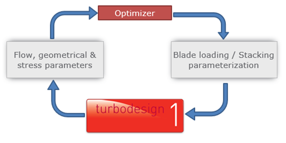
Figure 1: Workflow used in automatic optimization
Optimization Setup
The optimization process starts by specifying the range of variation for the input parameters, which are the streamwise loading as well as the shroud wrap angle (stacking) parameters as shown in Figure 2. Whereas by default the ranges are set to ± 10% of the original value for each parameter, a machine learning-based feature in TURBOdesign1 can provide optimized range estimates for these streamwise loading parameters. This is because we want to explore a large design space but also try and avoid infeasible solutions.
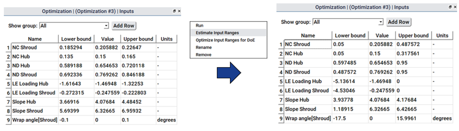
Figure 2: Default (left) and optimized (right) input parameter ranges used in automatic optimization
Figure 3 shows the constraints that were imposed on the optimizer as follows:
- the throat is limited to ± 5% to maintain the flow rate and so effectively the turbine power
- secondary flow factor is limited to avoid very high values
Finally, the optimization objectives are selected as follows:
- minimize the total profile loss to increase the runner's efficiency
- maximize the minimum pressure in order to remove the cavitation scenario
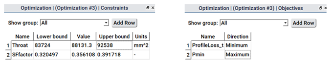 Figure 3: Constraints and objectives used in automatic optimization
Optimization Results
Once the optimization run is complete, which is very fast and only takes about an hour or so on a single core machine, all the design candidates can be seen on a scatter plot between the two objectives as shown in Figure 4. The position of the baseline runner relative to the candidates may also be noted.
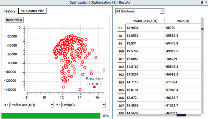
Figure 4: Scatter plot of all optimization designs
Next as Figure 5 shows, we can choose to see the Pareto front of optimum designs from which we can pick and analyse any design of interest. For the present study, we select a design from the middle of the Pareto front, which promises a good trade-off between the profile loss (efficiency) and the minimum pressure (cavitation). So we use this design for further analysis and for comparison with the baseline runner.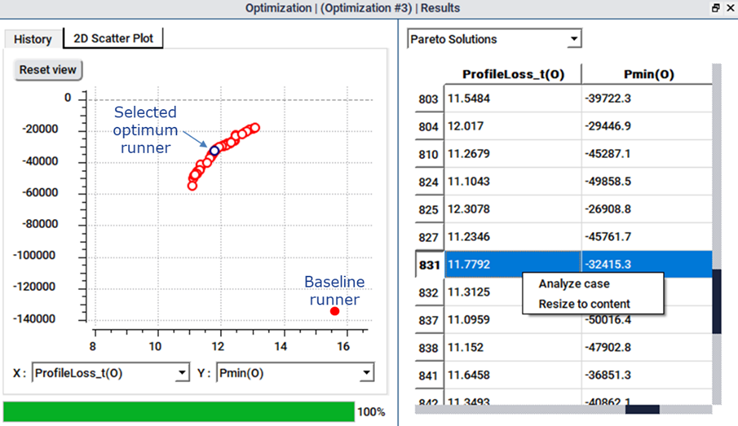
Figure 5: Pareto front of optimum designs
Figure 6 reveals what changed as a result of the optimization. The optimizer attempts to make the shroud more aft-loaded for the streamwise blade loading than the baseline runner to reduce the profile loss. Furthermore, while the baseline runner had zero stacking at the leading edge, the optimizer resulted in a forward stacking of 8 degrees. Consequently, the optimized runner is clearly looking very different from the baseline, and the surface pressure jump is reduced in the front portion of the runner compared to the baseline. This eventually results in positive pressure throughout this area thus eliminating the risk of cavitation in this region.
Figure 6: Comparison of blade loading and surface pressure between baseline and optimized runner
It is interesting to see the effect on the TURBOdesign1 performance parameters where there is a significant reduction in the total profile loss as a result of the optimization, with only a slight change in the throat area. When CFD analysis is performed on the new runner, there is about a 1 percentage point improvement in the total-to-total and total-to-static efficiencies of both the runner and the stage and a corresponding increase in the turbine power output. Furthermore, CFD pressure distribution confirms that just as the inverse design had predicted, the surface pressure stays above the vapour pressure throughout the suction surface, eliminating any chances of cavitation in the runner.
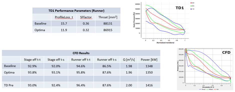
Figure 7: Results comparison between baseline and optimized design
Conclusion
Loss mechanisms in hydraulic turbines are typical of their specific speeds, and therefore is important to identify critical sources of loss mechanisms for your particular Francis turbine. In addition, extra attention should be given to cavitation requirements which affect the entire specific speed range. A good understanding of flow physics gained from CFD and experiments makes it possible to arrive at optimum blade loading for your Francis turbine:
- Streamwise loading distribution should be aft-loaded at the shroud
- Forward stacking at the leading edge should be applied
A major advantage of this approach is that the optimum blade loading for a particular flow phenomenon (e.g., profile loss suppression and cavitation control) has generality and can be applied regardless of the hydraulic turbine speed or size.
Watch Webinar on The Efficiency Improvement and Cavitation Control of Francis Turbine Stages by TURBOdesign Suite

Book a LIVE demo on the design of a turbomachinery application of your choice.
Our demo is tailored to your specific application and design challenges


Share This Post