In the first part of this article on the design of an axial turbine rotor, we showed that both aerodynamic and mechanical aspects of the baseline rotor need to be addressed.
In this second part, also based on one of ADT’s technical papers that was presented at the ASME Turbo Expo 2023 [1], we demonstrate the use of Optima feature in TURBOdesign1 to rapidly optimize the baseline rotor and achieve a simultaneous improvement in its aerodynamic performance and structural integrity.
Optimization Workflow
Figure 1 displays the workflow used by the automatic optimization, where the blade loading and stacking parameters are used to generate the blade shape in TURBOdesign1, and then the resulting performance parameters are fed into Optima which basically applies MOGA to drive the solution towards the optimum design.
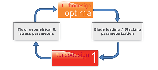
Figure 1: Workflow used in automatic optimization
Optimization Setup
The optimization process starts by specifying the range of variation for the input parameters as shown in Figure 2:
- streamwise loading parameters at the hub, midspan and shroud
- thickness scaling factor at the hub and shroud because it has an influence on the blade stress
In fact, with inverse design, these 14 degrees of freedom are sufficient to cover a vast design space and furthermore, given that the spanwise work is fixed, the computational time will be focused on the better areas of the design space. Next, the constraints are specified as follows:
- throat is tightly constrained to within 1.5% maintain the same mass flow rate as the baseline design
- maximum surface Mach number is restricted to suppress shock losses
- overall diffusion ratio is limited to avoid flow separation
- an upper limit is placed on the hub cross section area so that the optimizer does not increase it excessively to reduce blade stresses
Finally, for the optimization objectives we want to:
- minimize the profile and endwall losses which are calculated from surface isentropic velocities available from the inverse
design solver as shown alongside, which is of course in order to maximize the blade efficiency - minimize the maximum lean which creates bending stress due to the misalignment between the centrifugal force and the radial line
- minimize the centrifugal stress which is estimated from the hub cross section area and the centroid radius as shown alongside
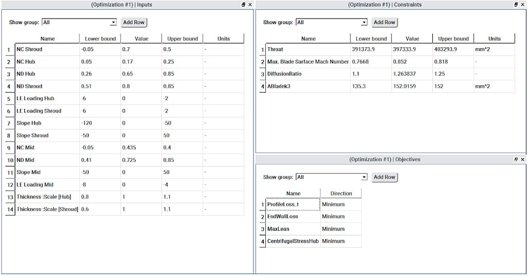
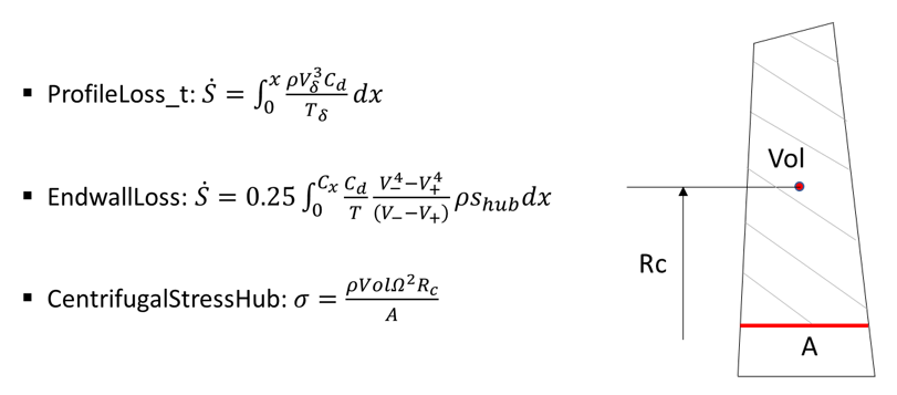
Figure 2: Inputs, constraints and objectives used in axial turbine rotor optimization
In this way, using a combination of aerodynamic and mechanical parameters, we ensure that blade integrity is not compromised in the process of improving its aerodynamic performance.
Optimization Results
Once the optimization run is complete, which is very fast and for 1600 designs takes less than 8 hours on a single core machine, we can see all the designs on a scatter plot between any two objectives as shown in Figure 3, where we have the profile loss on the X axis and the endwall loss on the Y axis, and the bubble size represents the other two objectives of centrifugal stress and maximum lean. Here we have chosen to see only the feasible designs which respect all of our specified constraints, and from which we can pick and analyze any design of interest. In this case, a design is selected from close to the Pareto front for a good aerodynamic performance, and with a relatively small bubble size to ensure blade structural integrity, and so we use this design for further analysis and for comparison with the baseline rotor.

Figure 3: Scatter plot between profile loss and endwall loss of feasible designs
Figure 4 reveals what changed as a result of the optimization. The optimized rotor features a smaller thickness especially from midspan to shroud. For the streamwise blade loading, along with a positive incidence throughout the leading edge, the optimizer recommends an aft-loaded hub and relatively fore-loaded midspan and shroud. As a result, the optimized profiles at the various spanwise locations are clearly looking very different from the baseline rotor particularly at the higher spans as shown alongside.
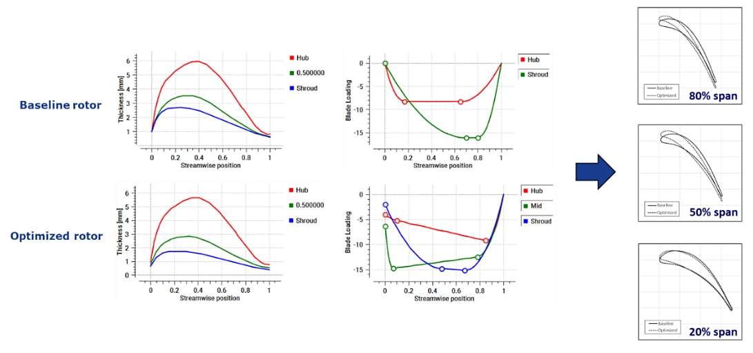
Figure 4: Comparison of spanwise work and blade loading between baseline and optimized rotor
Optimized Rotor Performance
The mechanical performance of the optimized rotor is investigated first. As Figure 5 shows, so far as TURBOdesign1 performance parameters are concerned, there is a substantial improvement in the stress related parameters with the hub cross section area staying within acceptable range. Even though the stress distribution in the FEA results is similar to the baseline rotor with peak stress at about 20% span location, the plot of average stress along the blade span provides final confirmation that the overall stress levels are noticeably lower in the optimized rotor.

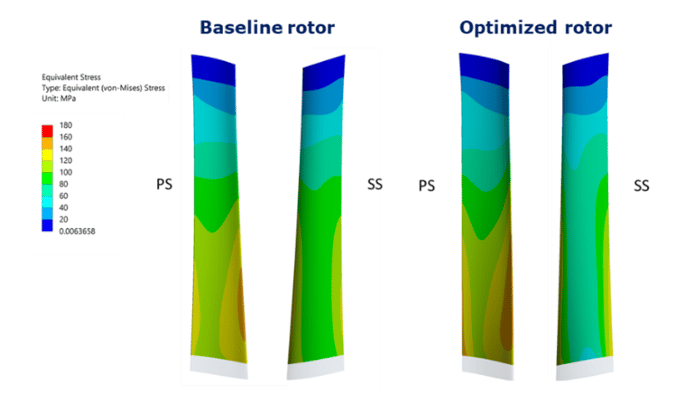
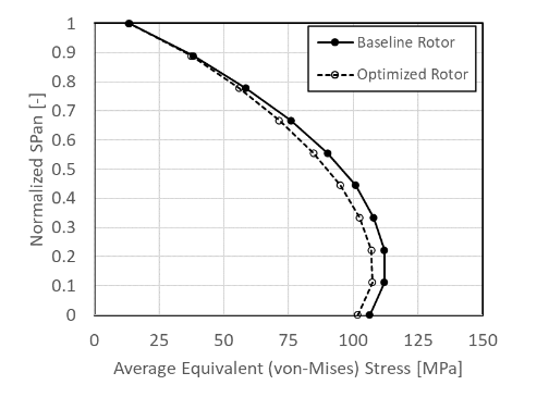
Figure 5: Comparison of TURBOdesign1 mechanical parameters, von-Mises stress contour and average equivalent stress between baseline and optimized rotor
Finally, what remains to be verified is the aerodynamic performance of the optimized rotor. Figure 6 presents the effect on TURBOdesign1 performance parameters where there is a significant reduction in the profile and endwall losses as a result of the optimization, while the diffusion ratio and throat remain within acceptable range. When stage CFD is performed with the optimized rotor keeping the stator the same as the baseline stage, it is found that there is a noticeable enhancement in the stage efficiency across the entire operating range, reaching up to 1 point increase at the lower pressure ratios. At the same time, the mass flow rate stays coincident with the baseline rotor at all the pressure ratio conditions, and a close match can be observed with the work coefficient of the baseline rotor at both leading and trailing edges.
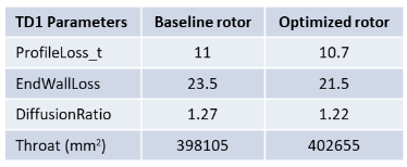
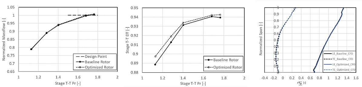
Figure 6: Comparison of TURBOdesign1 aerodynamic parameters, stage mass flow rate and total-to-total efficiency, and work coefficient between baseline and optimized rotors
In order to understand this stage efficiency improvement with the optimized rotor, Figure 7 reveals that its maximum surface Mach number in TURBOdesign1 is smaller than the baseline rotor. Finally, actual CFD comparisons make it evident that due to the upstream shift in loading, the peak Mach number value is reduced to well below 1 throughout the blade span. This is a clear indicator that the transonic losses have improved in the optimized rotor leading to its superior efficiency levels.
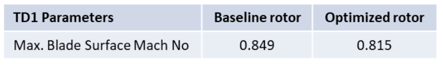
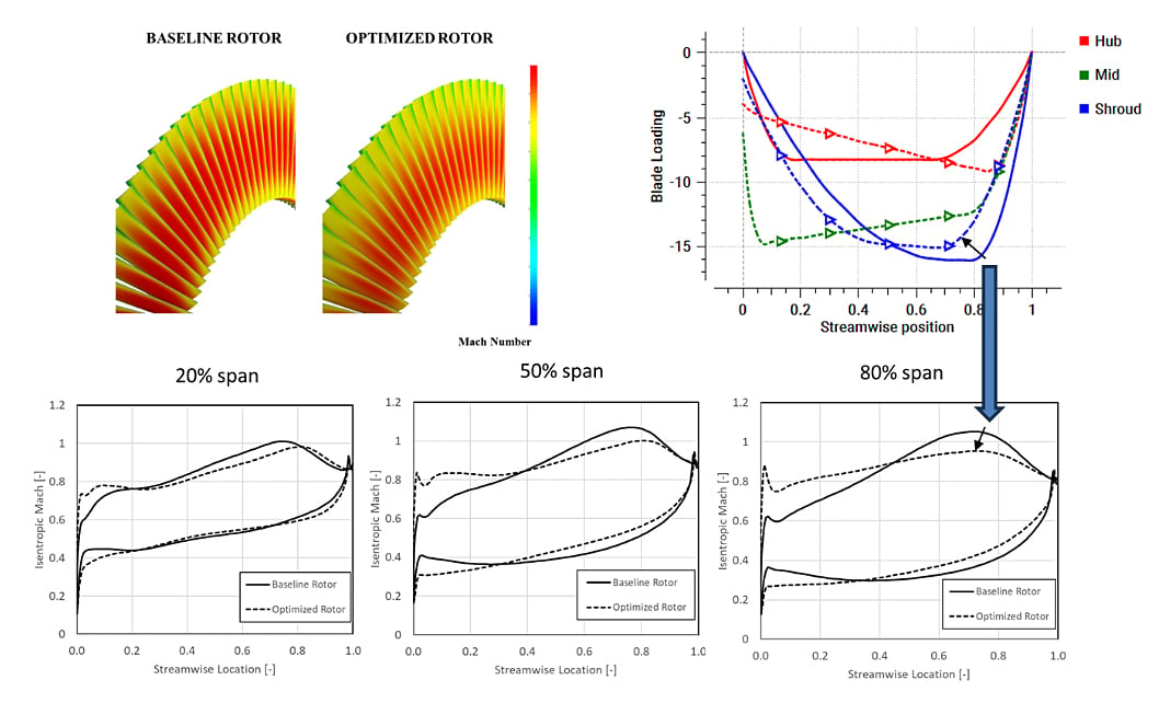 Figure 7: Comparison of TURBOdesign1 maximum Mach number and CFD Mach number distribution between baseline and optimized rotors
In this way, the rapid multidisciplinary optimization methodology is able to simultaneously enhance the aerodynamic and mechanical performance of the baseline rotor. The optimization takes less than 8 hours to complete and only a few CFD and FEA runs are required to achieve and verify the improvements:
- 10 CFD runs (5 baseline rotor + 5 optimized rotor)
- 2 FEA runs (1 baseline rotor + 1 optimized rotor)
Software Demo - Automatic Optimization of Axial Turbine Rotor
Conclusion
High speed low pressure axial turbines typically present a trade-off between the aerodynamic and structural aspects of the rotor. Essentially, using a combination of aerodynamic and mechanical parameters computed from inverse design, it is possible to optimize the rotor and achieve this trade-off in a matter of hours. Moreover, this methodology involves very less computational resources in terms of CFD and FEA runs compared to conventional design methods. Our experience has shown that the choice of optimum loading for controlling profile loss or secondary flows has generality and can be applied to other similar applications. For example, we find that for profile loss control, the type of loading that we use for turbines is applicable to all types of turbines, mixed flow and axial and regardless of the turbine speed or size.
References
[1] Zhang, L., Zangeneh, M., “Multidisciplinary Optimization of a High-speed Low Pressure Turbine Rotor Using 3D Inverse Design Method”, Proceedings of ASME Turbo Expo 2023, GT2023-102007, June 26-30, 2023, Boston, Massachusetts, USA
Book a LIVE demo on the design of a turbomachinery application of your choice.
Our demo is tailored to your specific application and design challenges


Share This Post