
A 3-D inverse design method provides better cavitation control and reduces manufacturing costs
Cost reduction is a driving force in pump design. The manufacturing cost of centrifugal and mixed pumps generally varies with the volume of the pump. To reduce manufacturing costs, the pump diameter must be reduced for a given head which results in an increase in head coefficient. Generally, an increase in head coefficient can lead to a reduction in efficiency and suction performance. The effect on suction performance in particular can be significant and is one of the limiting factors in the reduction of pump volume and, therefore, manufacturing costs. As a result, a key factor in the development of compact, mixed-flow and centrifugal pump stages is better control of cavitation.
Traditionally, mixed-flow and centrifugal pumps are designed based on empiricism and a trial and error approach, in which the impeller and diffuser geometry are modified manually by changes to the blade angle distribution. The flow through the pump stage is then computed by using 3-D computational fluid dynamics (CFD) code to evaluate the performance of the pump stage. The designer must rely on trial and error to make changes to the geometry to improve the performance of the stage.
However, a trial and error process restricts designers to a relatively small part of the design space, limiting them to blade angle distributions that have worked in the past. In addition, the process does not allow for the easy exploitation of a wide part of the design space to meet the contrasting requirements on efficiency and suction performance.
3-D Inverse Design
An alternative approach to the design of the pump stage is to use an inverse method. With this approach, the impeller or diffuser geometry is designed for a specified pressure distribution or blade loading. Since the viscous losses and cavitation behaviour in the pump is to a large extent controlled
by the 3-D pressure distribution, a designer can obtain more direct control over the design process by using this method.
Cavitation Control
A 3-D inverse design method has been used extensively for the control of pump cavitation. For example, it was used for the design of a high specific speed, mixed-flow pump stage to improve stage efficiency and reduce cavitation. By using the 3-D inverse design method, significant improvement of stage performance was possible, and cavitation was simultaneously suppressed at design operating conditions.
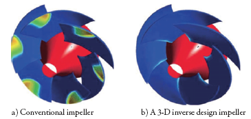
Figure 1. Contour of volume fraction of vapor as predicted using two-phase CFD analysis at design inlet pressure.
Figure 1. shows the volume fraction of vapour present on the suction surface of an impeller designed using a conventional method and one using inverse design. The flow in impellers was predicted by a two-phase CFD analysis. The blue region is non-cavitating, and the green and red represent regions of the high void fraction. Cavitation has been well suppressed in the inverse designed impeller with almost the entire blade surface being cavitation free.
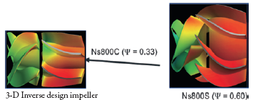
Figure 2. A comparison of the 3-D geometry of a compact stage designed using a 3-D inverse design method versus the original bassline mixed flow designed using the conventional method.
Volume Control
In another application, a 3-D inverse design method was used to reduce the volume of a medium specific speed, mixed-flow pump stage to 39% of a conventionally designed stage (see Figure 2). Test data confirmed that the redesigned stage can provide the same head, efficiency and suction performance at design point as the conventional stage with a 61% reduction in the volume of the stage. The code has also been used by the Japanese space agency, JAXA, to develop a compact design of a rocket pump.
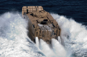
Image 1. Prototype of the EFV Amphibious vehicle with twin waterjects designed by a 3D inverse design method.
Waterjet Design
In addition, this method has been used for the design of mixed flow and axial pump stages for waterjets used by the U.S. Marine Corps’ EFV Amphibious vehicle by Honeywell, U.S. Navy’s David Taylor Research Center and CDI Marine (see Image1). The main objective was to develop a highly compact design to accommodate space limitation and to reduce entrained water.
Book a LIVE demo on the design of a turbomachinery application of your choice.
Our demo is tailored to your specific application and design challenges


Share This Post