Across the specific speed range, pumps are subject to various flow phenomena and loss mechanisms which are dominant in that particular range. For example, leakage and secondary flow effects are more dominant in lower ranges, whereas profile losses and corner separation in diffusers take priority in the higher ranges. In this article, we focus on secondary flow effects and how to come up with a set of optimal design guidelines to suppress this particular loss mechanism in a pump.
Secondary Flows in Impellers
Figure 1 shows a conventionally designed pump impeller with a specific speed of 280 (m, RPM, m3/min). CFD prediction of this conventional design very close to the suction surface reveals quite strong secondary flows inside the boundary layer, which carry the low momentum fluid on the suction surface and dump it onto the shroud suction surface corner. In fact, the exit flow from the impeller shows the accumulation of this low-momentum fluid resulting in a high-velocity region at the hub pressure surface corner. This flow non-uniformity at the exit of the impeller is known in the literature as “jet-wake flow” and has a major adverse effect on the performance of the pump stage for the following reasons:
- Creation of high-stage losses because of the mixing losses
- Poor performance of the downstream diffuser
- Source of pump instability that can affect the stall performance
It can also be observed that the gradients of reduced static pressure on the suction surface correlate quite well with the region of strong secondary flows. Consequently, if these gradients of reduced static pressure can be smoothed, then it should be possible to reduce secondary flows and thus eliminate this non-uniformity which is very important for the impeller and stage performance in pump applications.
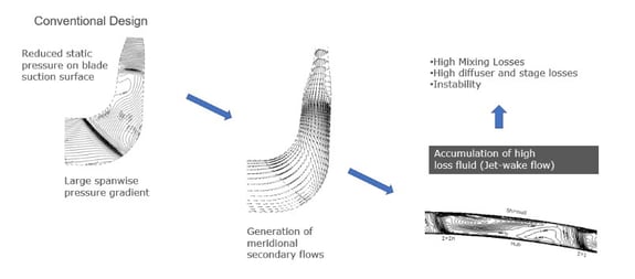
Figure 1: Conventional impeller flow field
Blade Loading
Figure 2 shows the reduced static pressure coefficient (Cp) on the hub and shroud on the same plot. These plots closely relate to the blade surface velocity and can be directly generated using any CFD software. Essentially, the difference between Cp on the suction surface of the hub and the suction surface of the shroud is what creates these gradients of reduced static pressure and drives the secondary flows. Thus, the ideal blade loading should try to reduce this difference as much as possible but in a way that ensures that the impeller head is not affected. In fact, in inverse design, it is possible to control the blade loading, which directly relates to the pressure jumps across the blade at the hub or shroud. Therefore, the appropriate choice of blade loading should:
- reduce the gap in the aft part of the shroud and increase it in the fore part
- increase the gap in the aft part of the hub and reduce it in the fore part
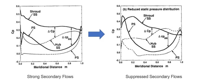
Figure 2: Reduced static pressure coefficient plots
Optimum Loading for Secondary flow control
Since blade loading is related to the difference between the pressure distributions of the suction and pressure surfaces of each, streamline the type of loading shown in Figure 3 can help to reduce secondary flows. This is because compared to the baseline impeller:
- fore-loaded distribution at the shroud reduces the surface velocities on the suction surface
- aft-loaded distribution at the hub increases the surface velocities on the suction surface
Therefore, this combination of a fore-loaded shroud and an aft-loaded hub makes it possible to achieve a net reduction in reduced static pressure gradients on the suction surface.
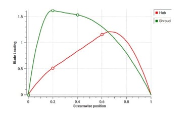
Figure 3: Optimum blade loading for secondary flow control in pumps
CFD Results for Redesigned Impeller
The effect of using the optimum blade loading for secondary flow control can be observed in Figure 4. The impeller shown has been designed maintaining exactly the same meridional shape and head as the baseline impeller but by using the optimal set of blade loadings. As the figure shows, this made it possible to reduce the gradients of reduced static pressure, and as a consequence, the secondary flows on the suction surface were eliminated. This in turn, resulted in a much more uniform exit flow from the impeller.
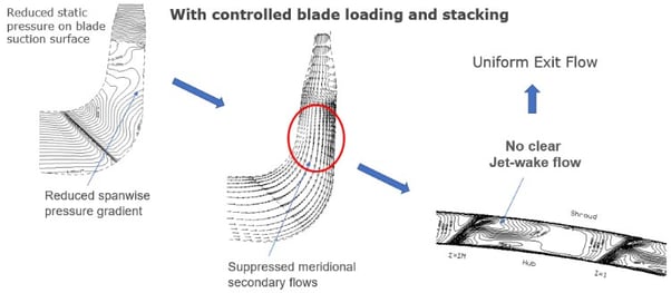
Figure 4: Redesigned impeller flow field
Book a LIVE demo on the design of a turbomachinery application of your choice.
Our demo is tailored to your specific application and design challenges


Share This Post