In the last blog, we highlighted the new modules in TURBOdesign Pre for the meanline design of axial fans and pumps stages and predicting the performance map of radial inflow turbines. In this blog, we will further discuss new features and functionality in TURBOdesign Suite v6.7 to enable designers to improve efficiency, achieve higher performance and deliver faster designs to achieve and maintain market-leading products.
What else is new?
Script version of TURBOdesign Pre
TURBOdesign Pre can now also be run in batch mode similarly to TURBOdesign1 script version. TURBOdesign Pre script version enables the user to run cases without interaction with the interface. It can be used to perform a high volume of calculations or to perform optimization calculations.
Improved mesh for blades with curved leading and trailing edge
The grid generated for cases which have curved leading and/or trailing edges has been improved by smoothing the mesh across the leading and/or trailing edge.
New geometry export functionality
The geometry export functionality of TURBOdesign1 has been enhanced with a new blade geometry construction procedure, as shown in Figure 7. The 3D blade geometry is generated by applying the normal thickness distribution directly to the 3D camber surface generated by TURBOdeign1, removing the problems found when making use of the tangential thickness. The highly refined thickness stored in the .geo files of version 6.7 also allows a much-improved definition of leading and trailing edges.
The leading and trailing edge modification can also be applied; this is performed by directly performing the elliptic modification to the thickness distribution. This approach is more robust than the Leading and Trailing Edge Modification tool, producing better results.
The export formats available are:
- Iges
- STEP
- TurboGrid
- BladeGen
Figure 8 and Figure 9 display geometries exported with the new functionality.
The conversion functionality is currently available only for geometries generated by the TURBOdesign1 solver version 6.7 and is not backwards compatible. As the geometry is built differently, it will slightly differ from those originally created by TURBOdesign1.
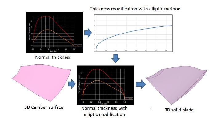
Figure 7: A new procedure to construct the 3D blade.
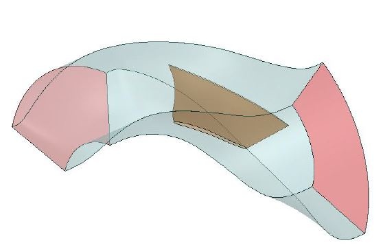
Figure 8: Computational domain for CFD analysis generated with the new geometry export functionality.
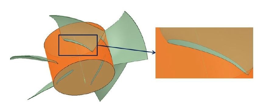
Figure 9: 3D solid blade geometry for axial fan generated with the new geometry export functionality.
Improved genetic algorithm optimizer
The multi-objective genetic algorithm used in TURBOdesign Optima (NSGAII) has been further enhanced and improved to provide a better spread of points on the Pareto Front with lower number of population size and lower number of generations hence improving the computational efficiency of the algorithm.
a) 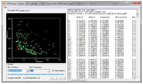 b)
b) 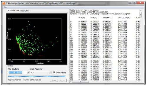
Figure 10: Optimization point distribution and parent front for population 20 and 20 generation. (a): Solution generated by version 6.6, (b): Solution generated by version 6.7.
Discover 6.7 update to TURBOdesign Suite's new features and functionality to enable designers to improve efficiency, achieve higher performance and deliver faster designs to achieve and maintain market-leading products.
Webinar: Introducing TURBOdesign Suite v6.7

- Learn the new features and functionalities in TURBOdesign Suite v6.7 to fasten the turbomachinery design and optimization process while achieving higher performances.
- Discover how a combination of fast meanline design and analysis along with robust 3D blade geometry modelling can streamline your turbomachinery development process.
- See how TURBOdesign Suite can seamlessly integrate with different CAE environments - Geometries exported with the new export procedure implemented in TURBOdesign1 are available to TURBOdesign Link for both ANSYS Workbench and STAR-CCM+.
- LIVE demo on the design of a turbocharger centrifugal compressor stage.
Book a LIVE demo on the design of a turbomachinery application of your choice.
Our demo is tailored to your specific application and design challenges


Share This Post