In another article on the manual redesign of a baseline axial fan, we showed how to manually set the spanwise and streamwise blade loading parameters in order to improve the fan performance from baseline to redesign 3.
This article examines the use of Optima feature in TURBOdesign1 to automatically optimize the blade loading of redesign 3 and enhance the performance even further.
Optimization Workflow
Figure 1 displays the workflow used by the automatic optimization, where the blade loading input parameters are used to generate the blade shape in TURBOdesign1, and then the resulting performance parameters are fed into the optimizer which basically applies MOGA to drive the solution towards the optimum design.
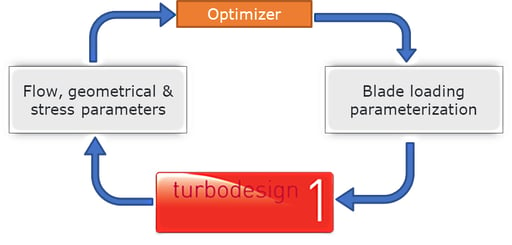
Figure 1: Workflow used in automatic optimization
Optimization Setup
The optimization process starts by specifying the range of variation for the input parameters, which are the streamwise loading as well as the spanwise rVt* distribution parameters as shown in Figure 2. Whereas by default the ranges are set to ± 10% of the original value for each parameter, there is a machine learning based feature in TURBOdesign1 that can provide optimized range estimates for these streamwise loading parameters. This is because we want to explore a large design space but also try and avoid infeasible solutions. However, the spanwise rVt* ranges are set manually where we extend the lower and upper bounds in order to provide sufficient play to the optimizer.
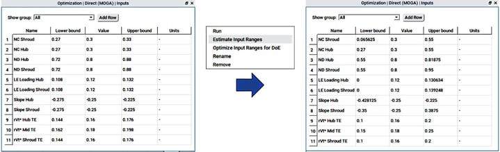
Figure 2: Default (left) and optimized (right) input parameter ranges used in automatic optimization
Figure 3 shows the constraints that were imposed on the optimizer as follows:
- throat is limited to ± 10% to control the peak efficiency point
- overall diffusion ratio is limited to avoid flow separation
There are also some Python scripted user-defined parameters for additional control:
- UD_work is indicative of the power consumption by the fan and so is constrained very tightly
- UD_overlapping is to avoid blade overlapping for manufacturing reasons, which is 1 for redesign 3 but needs to be 0 for the optimum design
- UD_NegativeBladeLoading parameters are used to prevent negative blade loading at the hub, mid-span and the shroud.
Finally, the optimization objectives are selected so as to minimize the total profile loss and the tip leakage loss since they are the dominant loss mechanisms in axial fans.
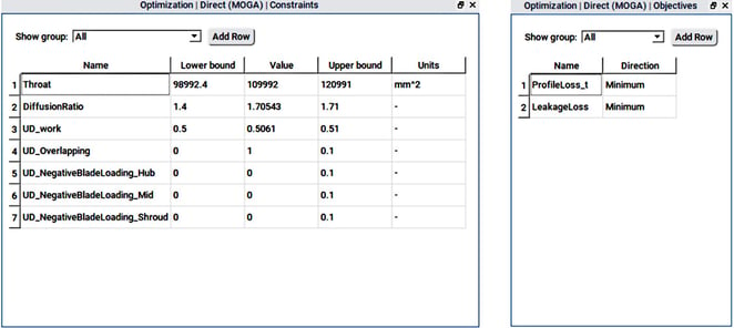
Figure 3: Constraints and objectives used in automatic optimization
Optimization Results
Once the optimization run is complete, which is very fast and only takes about an hour or so on a single core machine, all the design candidates can be seen on a scatter plot between the two objectives as shown in Figure 4. The position of redesign 3 relative to the candidates may also be noted.
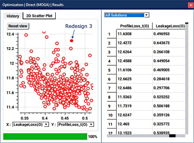
Figure 4: Scatter plot of all optimization designs
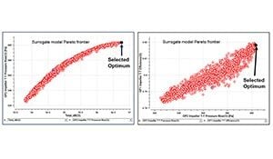
Next as Figure 5 shows, we can choose to see only the feasible designs which respect all the specified constraints. It also shows the Pareto front of optimum designs from which it is possible to pick and analyse any design.
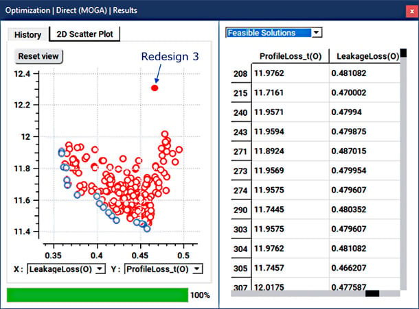
Figure 5: Scatter plot of feasible designs
For the present study, we select the minimum profile loss point as our optimum design for further analysis and for comparison with redesign 3, as indicated in Figure 6.
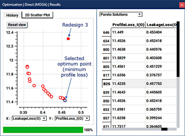
Figure 6: Pareto front of optimum designs
Figure 7 reveals what changed as a result of the optimization. For the spanwise work distribution, compared to redesign 3, the optimizer attempts to reduce the work at the hub and shroud in order to suppress the hub diffusion and tip leakage respectively. Consequently, as expected, it must raise the work near the mid-span in order to maintain the overall work. The blade loading also shows a considerable change from redesign 3, and as a result the optimized blade shape is clearly very different from redesign 3 as shown alongside.
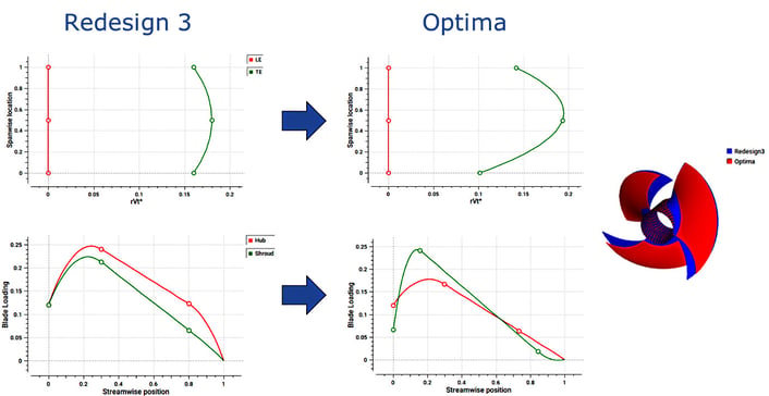
Figure 7: Comparison of spanwise work and blade loading between redesign 3 and optimized design
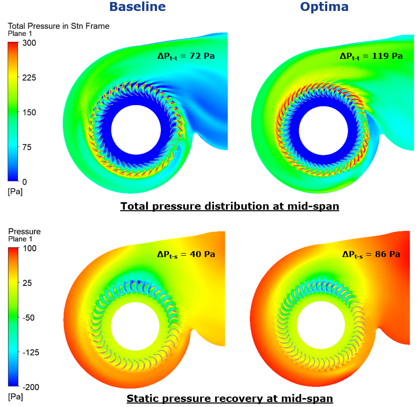
The results for the optimized fan are presented in Figure 8, where the TURBOdesign1 parameters reveal 16% lower overall diffusion ratio and 7% lower profile loss as a result of the optimization, without any compromise in the tip leakage loss. In addition, the front view of the different designs clearly shows that whereas there was significant blade overlap in the baseline fan and redesign 3, it is completely avoided in the optimized impeller as a result of the specified constraint on UD_overlapping. When CFD analysis is performed on the optimized geometry, there is a further improvement in the total-to-total efficiency of 1.6% point, bringing it even closer to the meanline estimate of 92% and resulting in a 21% increase in the total pressure rise.
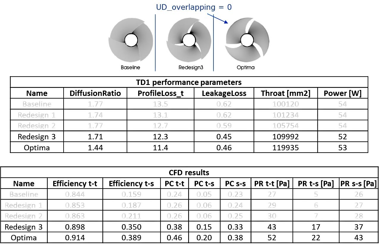
Figure 8: Results comparison between redesign 3 and optimized design
Finally, CFD runs are performed on the optimized design at three operating points (90%, 100% and 110% of the design flow rate) and the performance plots are shown in Figure 9. Clearly, the total-to-total efficiency is improved over the entire operating range considered. Furthermore, while redesign 3 achieves peak efficiency at 90% mass flow rate hinting at an undersized throat, the optimized design peaks at the design mass flow rate (1.58 kg/s) indicating that it has the correct throat area. A consistent increase in the total pressure rise over the operating range can also be observed.
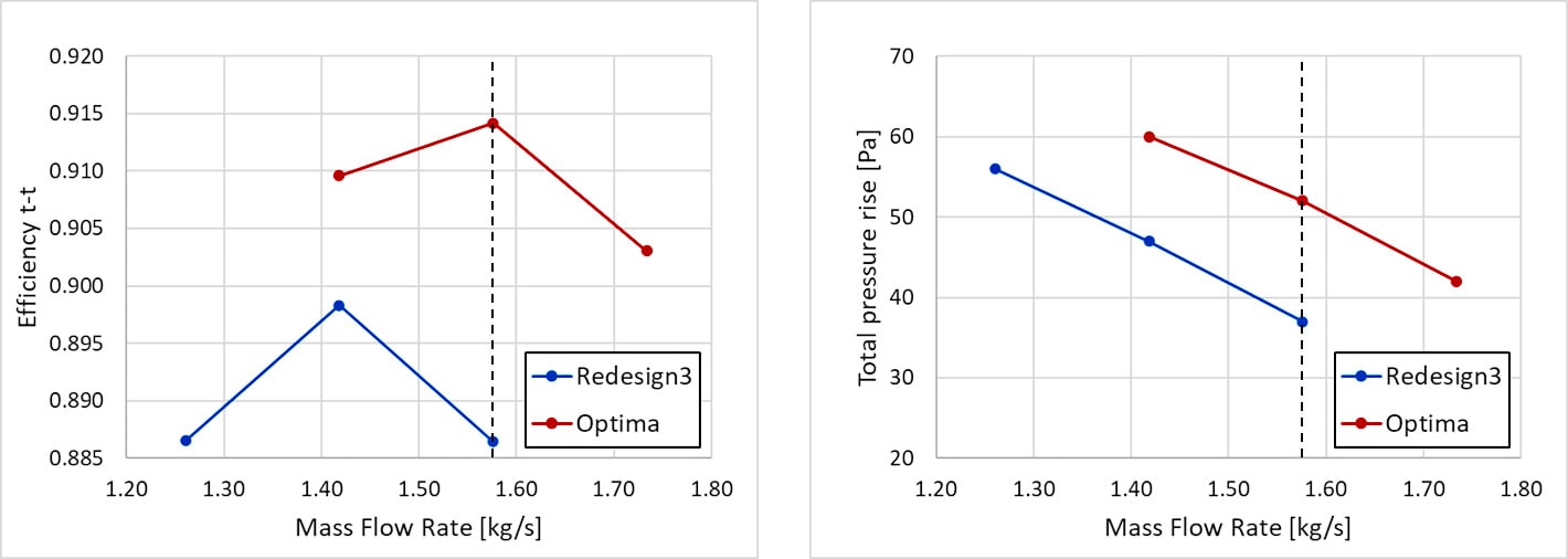
Figure 9: Performance plot comparison between redesign 3 and optimized design
Here's a Live Demo of the Automatic Optimization for Axial Fans
Conclusion
The study demonstrates that using direct optimization with purely the TURBOdesign1 output parameters and output velocity field, it is possible to drive a very quick optimization that can then be verified with CFD. This is because the geometry can be defined with very few parameters, and including blade loading parameters in optimizations is easily achievable. The study also proves that the inviscid flow parameters from TURBOdesign1 correlate strongly with the viscous performance predictions from CFD. As a result, an optimized fan design was obtained in merely an hour, and compared to the manually redesigned fan, both pressure rise and efficiency were further increased over the entire operating range considered.
Book a LIVE demo on the design of a turbomachinery application of your choice.
Our demo is tailored to your specific application and design challenges

Share This Post