The fan design process generally starts with the chart shown in Figure 1 which provides the relationship between speed number and diameter number as experimentally found by Cordier. This relationship, which is called Cordier-line in the literature, represents sort of “optimum” fans with high efficiency, and so there is a relationship between the speed number or diameter number and the type of fan to be used, whether axial, diagonal or radial, in order to obtain high efficiencies.
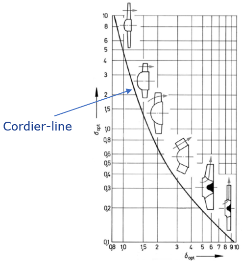
Figure 1: Cordier-diagram for axial, diagonal and radial fans
From the required speed number, we can identify the main flow phenomena and loss mechanisms dominant in that particular range. For example, incidence losses and flow separation usually take priority when it comes to Sirocco fans (or Squirrel Cage fans) which is the topic of this study.
From this information, we can use design tools and 3D CFD to investigate our fan designs, and what follows are a set of principal design guidelines based on the fluid dynamics considerations of reducing dominant flow losses for a given fan.
Baseline Fan - Meanline Design
Below are the specifications that are used to design the Sirocco fan stage, which consists of an impeller and a volute:
- Total pressure rise: 500 Pa
- Rotational Speed: 3000 rpm
- Flow Rate: 0.1 m3/s
Using our meanline code TURBOdesign Pre, it is very easy to enter the given specs and verify that it sits near the Cordier line, and then it quickly generates the meridional shape of the Sirocco fan stage in less than a second. As Figure 2 shows, it also provides a detailed report including the estimated stage performance and some important dimensions, as well as the required rVt* for the impeller. And this rVt* value is equivalent to the work coefficient and will be used for the 3D inverse design of the impeller wheel in the next section.
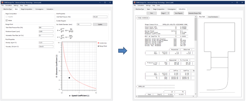
Figure 2: Meanline design of Sirocco fan stage in TURBOdesign Pre
Software Demo - Meanline Design of a Sirocco Fan with TURBOdesign Pre
Baseline Fan - 3D Blade Design
Figure 3 presents the setup for the baseline impeller, and the meridional design and other settings come from the meanline code as we saw earlier. It is also possible to specify your own custom thickness profiles which is very easy to impose as part of your inverse design process in TURBOdesign1, and is ultimately very important for structural considerations. The spanwise work distribution is free vortex, and so it has a constant value from hub to shroud. The default loading distribution is mid-loaded, and then these inputs result in this 3D geometry of the baseline impeller wheel as shown, along with some 2D plots such as the static pressure distribution on the blade surface.
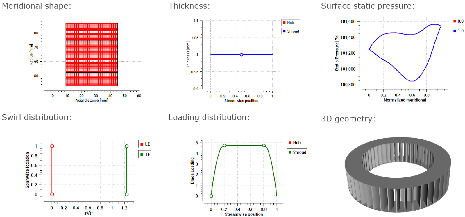
Figure 3: 3D blade design of Sirocco fan impeller wheel in TURBOdesign1
Software Demo - Design of Sirocco Fan Impeller
Baseline Fan – Volute Design
The meanline code also generates a volute report, and this information is used by TURBOdesign Volute to design the volute for the Sirocco fan. As shown in Figure 4, along with the main dimensions, it is also possible to define the cross-section shapes at the entry, duct and inlet which are selected as rectangular with rounded corners which is commonly seen in these fans. The most important input is the boundary condition at the volute inlet, that is, the radial and tangential velocity components, because then TURBOdesign Volute runs a 2D inverse design code to give the optimum cross-section area distribution for the given flow conditions at the impeller wheel exit.
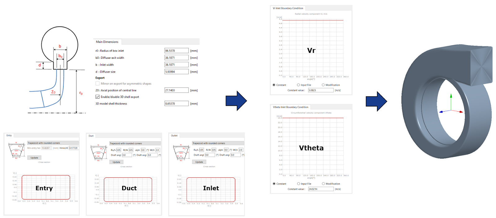
Figure 4: Sirocco fan volute design using TURBOdesign Volute
Software Demo - Sirocco Fan Volute Design with TURBOdesign Volute
Baseline Fan – CFD Setup
Once all the components of the Sirocco fan are ready, a stage CFD analysis is run to check the actual performance. As Figure 5 shows, we use ANSYS TurboGrid for the fully structured grid of the impeller wheel, ANSYS Mesh for the hybrid mesh of the volute, and CFX for the flow analysis. Following are the different CFD settings where the boundary conditions are chosen to match the inlet and outlet conditions in TURBOdesign Pre:
- P01, T01 = 1 bar, 300 K
- m2 = 0.1225 kg/s
- Impeller-volute interface = frozen rotor
- Turbulence model = k-omega SST
- Total mesh size ≈ 13 M
- Average blade y+ < 4
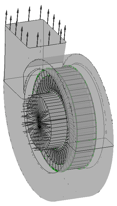
Figure 5: Sirocco fan stage CFD setup
Baseline Fan – Results
Figure 6 presents the different results for the baseline design. First there are the TURBOdesign1 performance parameters where we can see that the diffusion ratio is quite high. We also have the stage CFD results and clearly both total-to-static efficiency and pressure rise levels are low and also the total-to-total pressure rise is much lower compared to the target value of 500 Pa. A clear reason is the negative incidence at the blade leading edge resulting in a massive flow separation on the pressure side, and so clearly there is a scope for improvement in performance. The flow in the volute looks well-behaved though.
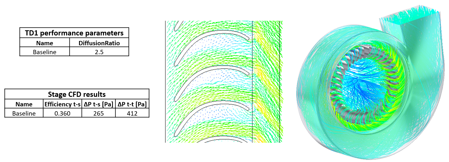
Figure 6: Sirocco fan stage pressure rise, efficiency and blade-to-blade flow vectors from CFD
In the second part of this article, we show how the stage total pressure target can be achieved through the application of manual redesign on the baseline impeller and volute.

Book a LIVE demo on the design of a turbomachinery application of your choice.
Our demo is tailored to your specific application and design challenges

Share This Post