In the first part of this article on the design of a Sirocco-type CPU cooling fan stage, we showed that there is scope for improvement in the baseline impeller especially in terms of achieving the stage pressure rise requirement.
In this second part, we show how the performance of the baseline stage can be enhanced to achieve the target through the application of automatic optimization on the baseline impeller.
Optimization Workflow
Figure 1 displays the workflow used by the automatic optimization, where the blade loading and stacking parameters are used to generate the blade shape in TURBOdesign1, and then the resulting performance parameters are fed into Optima which basically applies reactive response surface (RRS) to drive the solution towards the optimum design.
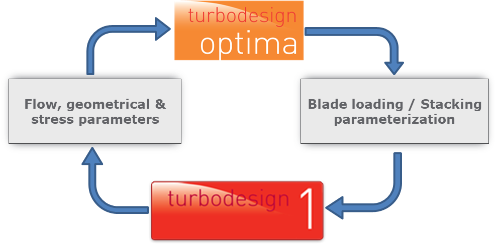
Figure 1: Workflow used in automatic optimization of CPU cooling fan
Optimization Setup
The optimization process starts by specifying the range of variation for the input parameters shown in Figure 2, which are the streamwise loading parameters and also the number of blades because it can also have a significant impact on performance. For the optimization objectives we want to minimize the profile loss and leakage to maximize the efficiency. But at the same time, we also want to keep the diffusion in check in order to suppress any flow separation.
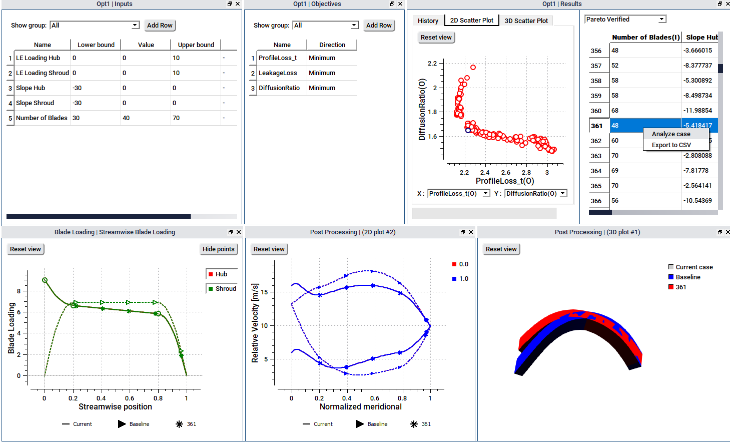
Figure 2: Inputs, constraints and objectives used in automatic optimization
Software Demo - Automatic Optimization of CPU Cooling Fan with TURBOdesign1
Optimization Results
Once the RRS optimization run is complete, which is very fast and only takes about 10 minutes or so on a single core machine, the design candidates can be seen on a scatter plot between any two objectives as shown in Figure 3, where the position of the baseline impeller relative to the candidates may also be observed.
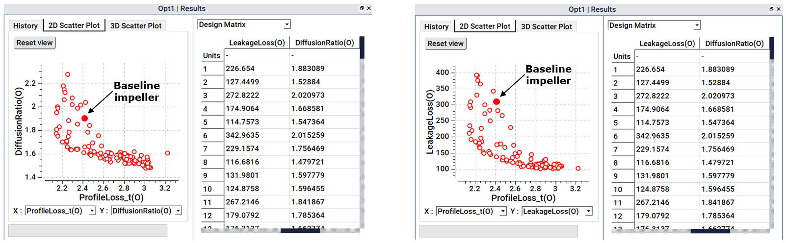
Figure 3: Scatter plots between diffusion ratio, leakage and profile loss of feasible designs
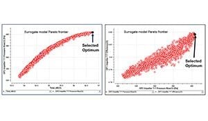
Next as Figure 4 shows, we can choose to see the Pareto front of optimum designs from which we can pick and analyse any design of interest. For the present work, we select a design which shows a considerable improvement in all three objectives, and so we use this design for further analysis and for comparison with the baseline impeller.

Figure 4: Pareto front of optimum designs with the selected design
Figure 5 reveals what changed as a result of the optimization. For the streamwise blade loading, compared to the baseline rotor, the optimizer recommends a high leading-edge loading along with a fore-loaded distribution in order to reduce the profile loss. Furthermore, the optimizer has increased the number of blades to 48 to control the diffusion ratio and leakage loss. As a result, the optimized blade clearly appears very different from the baseline as shown alongside.
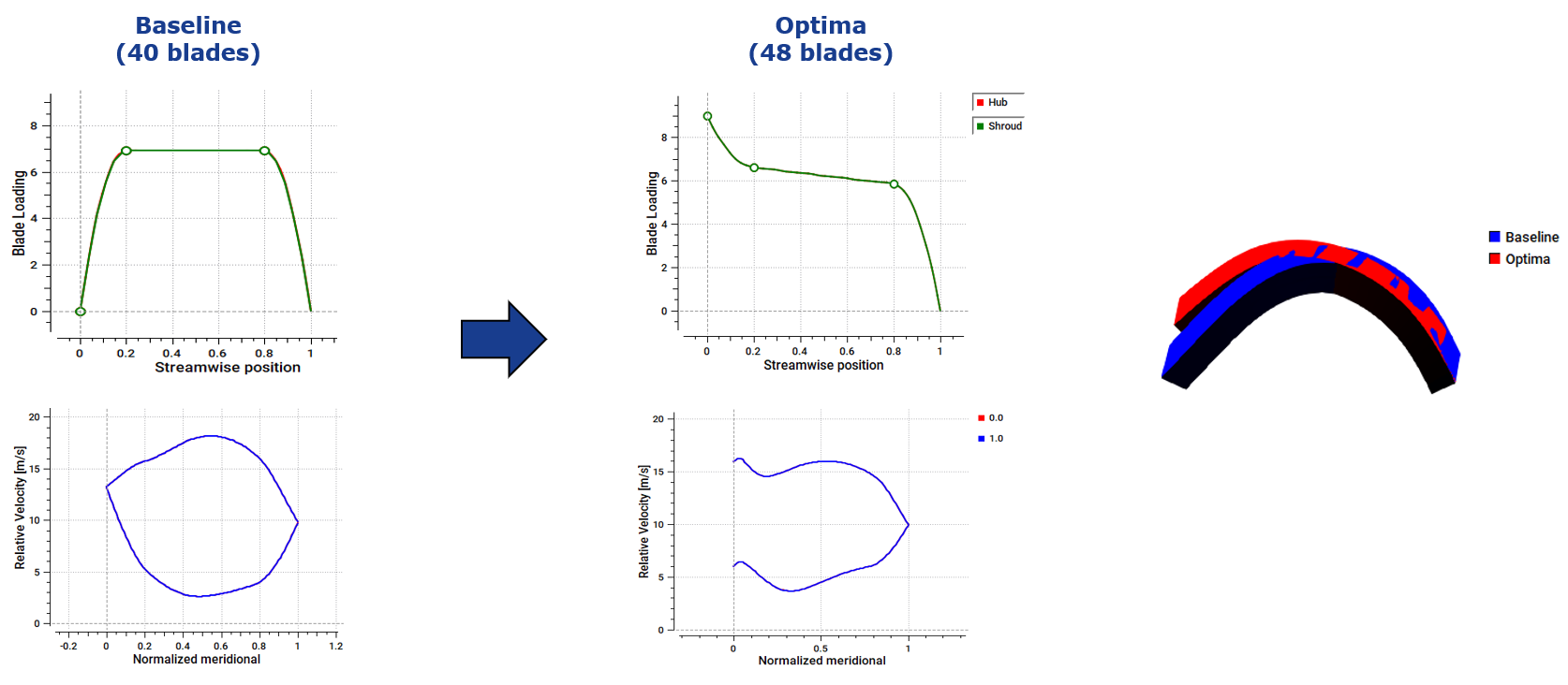
Figure 5: Comparison of blade loading between baseline and optimized impeller
As reported in Figure 6, it is interesting to see the effect on TURBOdesign1 parameters where there is a significant improvement in all the performance parameters as a result of the optimization. And when stage CFD is run with the optimized rotor, it is found that the blade is now well-aligned with the incoming flow, and there is also a complete elimination of suction side flow separation which is due to this much lower diffusion ratio. Moreover, the higher blade number helps to better guide the flow through the blade passage, and as a result it improves the efficiency as well as the pressure rise levels significantly. And in fact, the total-to-static pressure rise is even higher than the target value of 72 Pa.
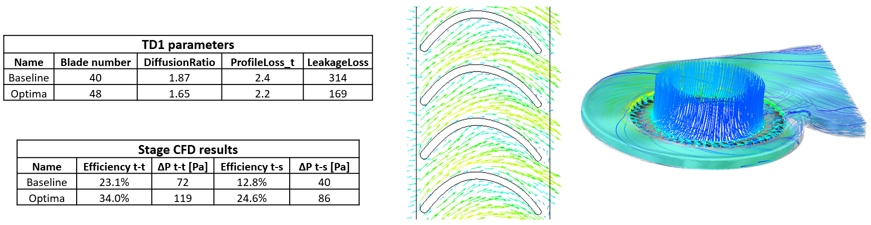
Figure 6: Pressure rise, efficiency and blade-to-blade flow vectors of optimized CPU cooling fan
Figure 7 presents some contour plots on a plane through the midspan, and clearly the flow coming out of the impeller is now much more uniform compared to the baseline. This has led to more energized flow in the volute with the removal of the low total pressure zones. It is also interesting to see the static pressure comparison, where there is higher pressure recovery in the volute with the optimized impeller which has a direct effect on the total-to-static efficiency of the fan.
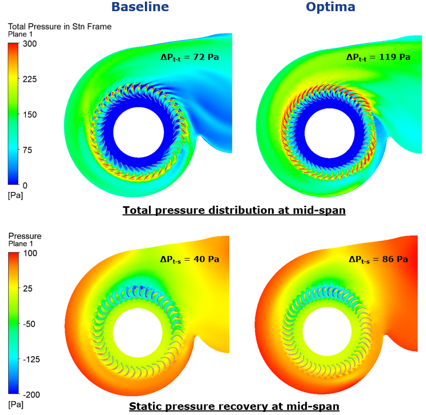
Figure 7: Contour plots of total and static pressure on mid-span plane through the CPU cooling fan
Conclusion
CPU cooling fans are a critical component of the E-cooling industry, but their design has unique challenges due to the extremely compact packaging requirement. Since the inputs to the inverse design method very directly influence the fan performance, it is possible to drive a rapid optimization using only inverse design parameters and arrive at optimum blade loading for your fan:
- Positive leading-edge loading should be applied
- Streamwise loading distribution should be fore-loaded at both hub and shroud
- Sufficient number of blades should be used
Our experience has shown that the choice of optimum loading for controlling incidence loss or flow separation has generality and can be applied to other similar applications. For example, we find that for profile loss control, the type of loading that we use for fans is applicable to all types of fans, mixed flow and axial, and regardless of the fan speed or size.

Book a LIVE demo on the design of a turbomachinery application of your choice.
Our demo is tailored to your specific application and design challenges

Share This Post