Across the specific speed range, pumps are subject to various flow phenomena and loss mechanisms which are dominant in that particular range. For example, leakage and secondary flow effects are more dominant in lower ranges, whereas profile losses and corner separation in diffusers take priority in the higher ranges.
However, a phenomenon such as cavitation is a major issue in the design of pumps across all specific speeds and applications. In many cases, it is necessary to achieve good cavitation performance while maintaining similar levels of pump performance. Furthermore, this is something that must be dealt with on a case basis and in this article, we focus on the specific case of a water jet with a fairly high specific speed and a fore-loaded impeller and how to come up with a set of optimal design guidelines to suppress this particular phenomenon.
Description of the Stage
The case in question is a mixed flow stage with a high specific speed of 946 (rpm, m, m3/min), 6 impeller blades and 11 diffuser blades as shown in Figure 1. It may be noted that the baseline stage already has high efficiency, and since there is often a trade-off between design choices for cavitation and efficiency, the purpose of this redesign is to find the optimum loading that can improve cavitation performance without an adverse impact on efficiency.
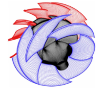
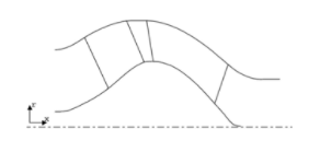
Figure 1: Baseline mixed flow stage 3D geometry and meridional view.
Parametric Study of the Loading Distribution
Since the baseline impeller is fore-loaded, a parametric study is performed by generating two new impeller designs, one with a mid-loaded distribution (LD1) and the other with an aft-loaded distribution (LD2) as shown in Figure 2.
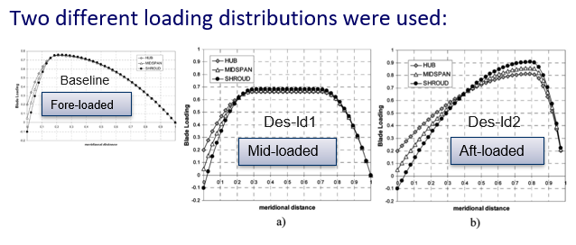
Figure 2: Blade loading on the baseline, LD1 and LD2 impellers
Stage CFD analysis is performed on the three impeller designs, and Figure 3 shows the impact of these loading changes on the blade static pressure distribution at the hub, mid-span and shroud. For the baseline case at the shroud suction surface, a sharp dip in pressure can be clearly noticed near the leading edge, and this is the chief cause of the cavitation problem. It can also be observed that as the loading shifts towards a mid-loaded or aft-loaded distribution, this dip is reduced further and further. Therefore, this should lead to improvements in cavitation performance.
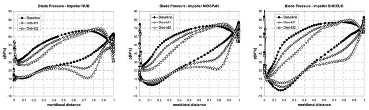
Figure 3: Static pressure distribution on baseline, LD1 and LD2 impellers
However, Figure 4 shows further results from the stage CFD analysis, which indicate that a design trade-off is necessary:
- Cavitation improvement is confirmed through an increase in NPSHR estimate based on power drop.
- However, there is a negative impact on the overall performance, as seen from the significant drop in stage efficiency.
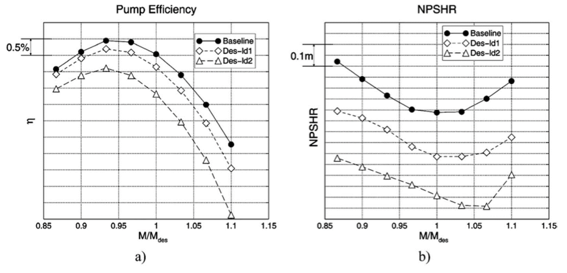
Figure 4: Stage CFD results of parametric study
Optimum Blade Loading
In order to achieve this compromise between cavitation and efficiency, the following type of loading distribution is adopted, as shown in Figure 5:
- fore-loaded distribution at the hub and the midspan, which rapidly diffuses the flow and ensures low profile losses and high efficiency.
- unloading the first 10% of the shroud and an almost fore-loaded distribution after that. This removes the dip in the static pressure that goes below the vapour pressure causing the cavitation problem at the shroud.
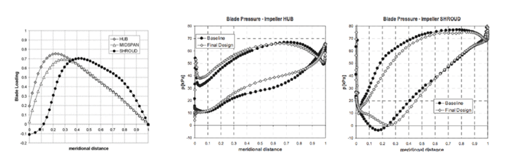
Figure 5: Optimum blade loading for cavitation control in pumps
Figure 6 confirms that the loading distribution described above is able to successfully achieve the desired trade-off. Although there is a minor drop of about half a per cent in the stage efficiency, there is a significant improvement in the NPSHR throughout the operating range.
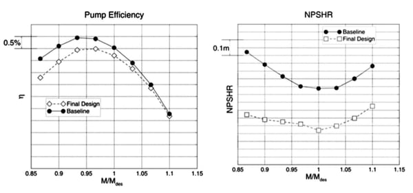
Figure 6: Stage CFD results of an inverse-designed impeller
CFD Predictions: Multi-phase Cavitation Analysis
The single-phase CFD results are verified through a multi-phase cavitation analysis, and Figure 7 shows the contours of the mass fraction of the vapour phase. Clearly, while the baseline impeller is seen to cavitate at the inlet design pressure, the new design shows no signs of cavitation. Moreover, at 60% of the inlet design pressure, while the cavitating region is expanded in the baseline design, it is much smaller in the new design. This is further proved through experiments in a cavitation tunnel, which shows a very good correspondence with the regions of cavitation predicted by the multi-phase CFD. 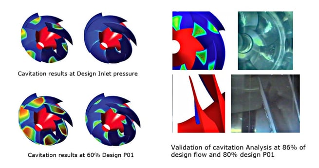
Figure 7: Multi-phase CFD analysis results and experimental validation
Conclusion
Our experience has shown that the choice of optimum loading for cavitation control has generality and can be applied to other similar applications. Thus, the type of loading that we use for cavitation control is applicable to all types of pumps, mixed flow and centrifugal. For example, the below images show the optimum loading repartitions for controlling the pressure distribution and improving the cavitation patterns in some of our consultancies in the past.
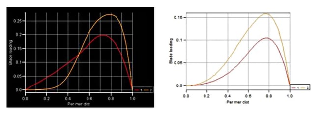
Figure 7: Optimum blade loading for cavitation control in an aero-engine fuel pump impeller (left) and a multistage pump inducer (right)


Book a LIVE demo on the design of a turbomachinery application of your choice.
Our demo is tailored to your specific application and design challenges


Share This Post