The 2026.1 release advances Physics-Enhanced Machine Learning (PEML) and universal CAE integration, allowing engineers to build highly accurate optimization models with smaller datasets.
-
TURBOdesign Suite 2026.1 is the Large Physics Model (LPM) Accelerator.
-
Expanded Ansys Fluent Integration: Direct automatic integration from inside TURBOdesign1, supporting all machine types, mesh formats, boundary conditions, and fluid states.
-
Open Machine Learning Framework: The Reactive Response Surface (RRS) machine learning engine now connects with any external platform, including custom in-house codes and open-source packages.
-
HPC Scalability: Native remote execution settings allow parallelized optimization jobs to be offloaded directly to remote Linux HPC clusters.
-
Advanced Modeling: Features new Inlet Guide Vane (IGV) compressor models, automated axial thrust calculations, and two-phase flow functionality.
-
Meanline Design Exploration: Introduces N-dimensional design space sampling (Latin Hypercube) to map variables before setting detailed 3D geometry
Key New Features and Advancements
The latest release of TURBOdesign Suite combines usability and application specific enhancements with a significant move towards enabling Physics-Enhanced Machine Learning within any and all Computer Aided Engineering (CAE) simulation environments.
Advanced Design Technology’s unparalleled knowledge and experience of the turbomachinery design process for all machine types has allowed us to view the burgeoning field of machine intelligence in real engineering processes with an expert's eye. We have developed this new version of TURBOdesign Suite as a way for users to build high-fidelity, small dataset machine learning systems that deliver true value and results based on sound hydro/aerodynamic first principles.
From this point, the user can build Large Physics Models (LPMs). LPMs are a new class of AI systems that are trained directly on physical data, simulations, and mathematical principles rather than human language (cf. Large Language Models, LLMs). They ultimately bypass traditional, time-consuming computational physics simulations, drastically accelerating engineering design and discovery.
How to overcome data bottlenecks in AI and machine learning for optimization?
In the machine intelligence ecosystem, a number of methodologies have emerged that might be applicable to the problem of creating a new turbomachinery component for a required range of performance specifications. However, there are serious limitations that need to be assessed before we jump on the hype-train of promised benefits.
Artificial Neural Network (ANN)
Traditional ANNs in turbomachinery function as purely data-driven surrogate models (geometry in -> flow field out). They require very large data sets (tens of thousands) to achieve accuracy for 3D optimization due to the non-linear mapping of the Navier-Stokes equations. Many geometrical data used to train the system will be completely infeasible as a potential solution but will be evaluated anyway. And as the ANNs have no knowledge of the underlying physics this leads to hallucinations (for example flow through a wall). This cost-benefit payoff makes ANN generally unsuitable for detailed engineering component design.

Figure 1: Pattern matching Artificial Neural Networks (ANN) require tens of thousands of datapoints to train a flow-prediction model
Physics Informed Neural Network (PINN)
ANNs can be augmented with the physics of the system they are evaluating. These then become PINNs. The governing physical laws (such as the Navier-Stokes equations) are directly embedded into the network's loss function during training. This approach avoids some infeasible designs because of the built in PDEs in PINN. But PINNs can be very unstable and difficult to train as different loss functions (e.g Ldata, Lpde, Lbc,etc) pull the optimizer for hyperparameters in different directions. PINNs also suffer from spectral bias, that is they struggle with shockwaves and high frequency wave propagation (conversely PINNs are quite well suited to smooth physics, e.g. heat conduction). Additionally they are difficult to construct for complex 3D geometry (due to the sparseness of co-location points) and are not at all suited to generalisation, even a change of operating point will require extensive retraining.

Figure 2: PINN’s reduce the training load somewhat by adding governing equations to the nodal weights
In both the above methods, the sheer cost of building and training these models means that it is nearly always more efficient just to brute-force (trial-and-error) your way to a new design using a much smaller number of simulations overall. Of course trial-and-error is wasteful, limiting and inefficient in its own right. So what is the way to unlock the power of machine learning whilst retaining accuracy, flexibility, in-built domain knowledge, and a reasonable simulation load?
Physics Enhanced Machine Learning (PEML)
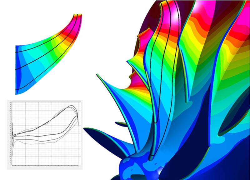
The unique 3D inverse design method, developed by ADT, is the key to achieving machine learning in turbomachinery design. Using the 3D inverse design as a generative engine for training automatically embeds the laws of physics into the candidate generation. So we do not have to infer the physics via pattern matching (ANN) or PDE loss function penalties (PINN). PEML only needs a small number of design parameters to cover a large design space - because parameterization via inverse design controls is incredibly efficient. All designs satisfy the correct specific work at the correct flow which completely removes infeasible designs from the training dataset (infeasible designs are not even created, let alone evaluated). So a very simple machine learning model, based on response surface fitting using very small data sets can achieve high accuracy ML models.

Figure 3: PEML requires only a small training dataset to fit a response surface
The key requirements for high accuracy small data set PEML are:
- Designs are parametrized by input to the 3D inverse design method, ensuring the correct specific work at correct mass flow
- A consistent set up for evaluation of performance parameters from CAE
- A well-conditioned machine learning algorithm
In TURBOdesign Suite 2026.1 there are many new features that make small data set high accuracy PEML for turbomachinery design optimization a possibility for even wider applications in turbomachinery.
What are the New Features in TURBOdesign Suite 2026.1?
RRS with Customer Own CAE
This new feature brings any and all CAE packages into the TURBOdesign Reactive Response Surface (RRS) PEML system. It allows TURBOdesign1 to externally share data with 3rd party packages, whilst internally creating the geometry candidates and running the exploration and exploitation of the design space.
TURBOdesign1 creates a design matrix (as a CSV file) and exports the indexed candidate geometries in a chosen CAD format (e.g. step file of the fluid passage) . The user runs their own CAE analysis on the geometries and returns the results to TURBOdesign1 via data entry in the CSV file. This can easily be automated using, for example, a python script to handle extracting the CAE result data and adding it to the CSV file.
TURBOdesign1 then builds a response surface from the data and starts to reactively explore the design space by exporting more geometries to be evaluated. Once this export-evalute-import cycle is completed, TURBOdesign1 has enough information to build the surrogate model and construct the Pareto front of competing optimal designs across multiple objectives and operating conditions. The final step is to select candidates from the Pareto front, export the geometry of these and make a final evaluation.

Figure 4: TURBOdesign1 builds a design matrix, the candidate geometries can then be evaluated in any CAE system and the results of the CAE analysis are stored in a common CSV file

Figure 5: The completed CSV file of the training dataset is imported back into TURBOdesign1

Figure 6: TURBOdesign constructs a surrogate model and Pareto front from the training dataset. From which optimal candidates can be selected and realised in CAD
Enabling this route into/out of TURBOdesign1 RRS means that any conceivable CAE variable (or combination of variables) can be used as objective or constraint during optimization.
TURBOdesign Pre Design Exploration
TURBOdesign Pre rapidly produces a flowpath design and performance prediction for any turbomachine from just a handful of basic performance specifications. In 2026.1 this is extended to run across a range of performance specifications and represent all the candidates in that range as design options. The ranged specifications can be as many as required - resulting in an N-dimensional design space. E.g. a range of pump speeds, target heads, and flow rates results in a 3-dimensional design space. This space can be populated using a full factorial approach (in which case the number of discrete points across each dimension are specified), or a Latin Hypercube sampling approach (in which case the total number of samples in the hypercube are specified).
In a few seconds the GUI presents the graphical representation of the relationship between 2 input or output variables, from which designs can be chosen and taken downstream.

Figure 7: TURBOdesign Pre allows the user to choose design specifications across ranges of values

Figure 8: The results can be visualised in a 2D plot of any pair of input or output variables
This extremely fast design space exploration allows the user to quickly place their design in exactly the required performance space before even moving on to the details of 3D blade shapes.
Other Improvements in TURBOdesign Suite 2026.1
For Centrifugal Compressors, Refrigeration and Heat Pump Cycle solvers, there is now an option to include a model of an Inlet Guide Vane (IGV) in the meanline calculation. The IGV is included in the performance prediction and the 3D geometry of the IGV can be created and exported from TURBOdesign1.

Figure 9: 3D model of compressor inlet guide vanes
For Centrifugal Compressors, Refrigeration and Heat Pump Cycle solvers, there is now an option to calculate axial thrust in the bladed region. And optionally on the backplate. The total axial thrust is the sum of these two values.There is also built in functionality to calculate thrust automatically using the 3D geometry and accurate surface pressure from TURBOdesign1.
The algorithm that predicts front leakage flow rate for centrifugal pumps is improved. Using data mining based on a large number of cases run in CFD (including the leakage model) to train the loss models in TURBOdesign Pre.

Figure 10: Improvement to the correlation of the pump leakage model blue v2025.2, orange v2026.1
TURBOdesign1 now supports performance calculation for two phase flow expansion turbines (e.g LP steam turbines or turbines used for heat pump applications.) The post-processing window includes plots of dryness fraction distribution on the blade surface and the new T-S Thermo diagram allows the user to visualize the expansion process. Properties are obtained from an RGP file.
Ansys Fluent is now included as an solver option for CAE Integration and RRS with CAE optimization - it supports:
- All machine types (and ‘generic’)
- All fluids (in/compressible, real gas)
- All boundary condition combinations
- Including inlet flow direction vectors
- K-epsilon and SST turbulence models
- Splitters, tip and hub gaps
- Uses Fluent polyhedral meshing
- Robust to highly-3D shapes, high curvature
- Uses SpaceClaim or Discovery as the CAD ‘bridge’ between TURBOdesign1 and Fluent
- Full turbo post-processing (html report)
CAE integration and RRS with CAE can now be run on remote Linux HPC Clusters.
In CAE Integration and Optimization (RRS with CAE) dialogs – the option ‘Remote Execution Settings’ gives options for connecting to a remote server. The system supports the PBS queueing system for multiple batch jobs with real-time monitoring when simulations are running.
TURBOdesign 2026.1 provides the functionality to run the CAE cases already set up inside a *.tds_project file in batch mode using the command line.
Optimizers now use ‘Outputs’ to build strategy. Select any and all parameters as ‘Outputs’. These can then be used as Constraints or Objectives. Any remaining outputs are kept as Monitors during optimization runs. Monitors are included in the design matrix data but are not used to drive the optimizer (they are ‘passive’) .Once the surrogate model is obtained, any Outputs can be used as new objectives and constraints to quickly explore a new design space.
2D and 3D Scatter plots from CAE integration or Optimization studies can now be displayed with colour and bubble size scalar modifiers to add more context to each plot.

Figure 11: Colour scalars on Design Matrix plots inside TURBOdesign1
When exporting CAD files, the option to Extend the blade at the hub, shroud and trailing edge in RZ is now available. In Export Settings, full wheel or single blade FEA type exports (i.e. the metal as solid) can be output as separate entities for blade , hub and shroud. This often aids meshing control and part management in downstream applications.

Figure 12: CAD models exported with separate entities for hub, blade and shroud
The introduction of these tools streamlines the entire workflow from preliminary design to high-performance remote cluster execution, allowing engineers to produce paradigm shifting designs in much shorter timescales.
Schedule a live demo tailored to your turbomachinery application.
We'll show you how to solve your specific design challenges.


Share This Post