Traditionally, the design and optimization of complex shapes have been computationally expensive and improvements gained via trial and error, which is also expensive and less efficient. TURBOdesign Shaper is a software product of Advanced Design Technology that targets to ease the design of complex geometrical shapes. It is a solution for sensitivity analysis and optimization with computational cost being independent of the complexity.
Shaper optimizes complex geometries with respect to given targets, such as total pressure loss and velocity uniformity. It does so by computing the sensitivities of the geometry itself versus those targets and then modifying it. The sensitivity information comes directly from the flow field so the optimized shape is the one that best fits the given flow. Also, the computations related with such a process are independent from the number of design variables, delivering the sensitivities or optimized shape at minimum cost.
Shaper vs existing methods
Although several industrially established methods exist for the optimization of relatively simple geometries (i.e. geometries that can be controlled via a very small number of design variables), there is none that can optimize complex geometries. That is because complex geometries need a high number of design variables so as to be controlled and that would be computationally prohibitive with existing methods. Therefore engineers rely on experience and trial-error experiments to modify complex shapes until now, although the potential for performance improvement from such parts is big.
Shaper introduces a new method which is independent of the number of design variables and can optimize arbitrary shapes at the same cost for any number of design variables.
Competitive advantages
There are numerous competitive advantages in using Shaper. Shaper is capable of complex geometry handling. Engineers using other methods for optimization have to simplify their models either because optimization would otherwise be very expensive or because the setup of the design parameters would be practically impossible. In Shaper, the computational cost will be the same, no matter how complex the geometry is. Also, the step of setting up the design is only a matter of seconds, as it will be discussed in the next section.
One of the most completive advantages of Shaper is the computation low cost of the optimization. The latter is independent of the number of design variables and the geometrical complexity, removing the worry of the designer to deliver new designs in time and with fewer resources.
Another advantage of Shaper is the straightforward design setup. In other software, the user needs to define control points, surfaces, etc, which take up a lot of time even for simple geometries. Such a setup is often impossible for complex geometries. Also, it removed the sense of direct control over the surfaces of interest and makes it diÿ cult to set the appropriate constraints, as they no longer depict on the actual surfaces but on the control surfaces. In Shaper on the other hand, design surfaces are picked by name and the software itself defines all surface nodes on the latter as design variables. This way is not only exceptionally fast to set up but also makes the constraints easy to impose.
With the use of Shaper, the designer can reach innovative designs. With no constraint on the number of design variables, the design space will be larger than ever before. New shapes and ideas can be generated in a matter of minutes or hours, giving a competitive advantage to the users of the software.
Perhaps one of the most important aspects of Shaper is that it results in manpower and design time savings. The traditional trial and error methods of design are very time consuming and take up a lot of manpower resources. Also, it is not guaranteed that they will result in an improved design or that the design they produced is actually the best possible. Instead of this, Shaper can provide an accurate mathematical approach, drive the design to the best shape when used in optimization mode or provide detailed sensitivity information that would assist the manual design process.
Last but not least, Shaper aims for seamless integration into existing processes. It import and exports results in the CGNS file format, which is supported by all major software. In this way, users can create computational meshes and also post process results in any of the dedicated software that they are accustomed to. In this way, investments in other software, training and experience gaining are not lost. Also, this removes any learning curve for Shaper, which is deliberately designed to be simple and drive the workflow.
Design process
The design process of Shaper is kept simple on purpose. The target is to ease the design processor and only act as a simple handy tool for the engineer and designer. Therefore, the process is fairly similar to the one used for a simple CFD solver and only requires a single extra step.
The first step is to create a computational mesh. Shaper is not shipped with its own meshing capability, as most of the engineering companies have already invested in meshing software and relative training. In this way, existing knowledge and experience is not lost. Shaper will import any mesh in CGNS file format, which is supported by all major mesh generation software.
The second step is to import the created mesh in Shaper and set the boundary conditions. Once imported, Shaper recognises the names of the boundaries, as given during the meshing process.
Boundary conditions can then be set for each boundary.
In the third step, the parameters for the flow solver are set. At this point, the flow solver of Shaper is an incompressible Navier - Stokes solver.
The only extra step is to set up the design, which is particularly straightforward. The user simply has to select which of the named boundaries will be design surfaces, set the relative min and max constraints (if any) and pick the desired cost functions.
With everything set up, Shaper can now complete any of the available tasks. Most interesting are the sensitivity computation and optimization. The first would provide sensitivity information on the given geometry with respect to the given cost function(s) whereas the second would go further to modify the original geometry based on the sensitivity information.
Many engineers prefer to see the sensitivity map and apply manual changes based on the latter and also their opinion. If optimization is selected though, Shaper will modify the geometry towards a better performing shape. It shall be highlighted here that Shaper will maintain the mesh quality during the design process and no re-meshing is required after each design step.
Regardless of which task is selected, Shaper will output the results in CGNS format for post processing. This is again in the same logic with meshing. All major post processing software support the CGNS file format and the designers are already accustomed to some of those. Therefore, there is no learning curve for post processing either. Engineers can view flow and sensitivity results directly in the software they are used to.
Examples
Automatic design variables
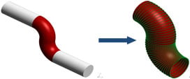
Figure 1: All the nodes on the (red) boundary are design variables.
All mesh nodes laying on boundaries that have been selected for design will automatically be considered as design variables. These could be hundreds or thousands but the cost will remain the same. This approach makes it easy and fast for the user to set up.
Sensitivity maps
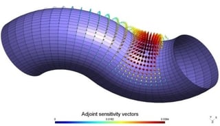
Figure 2: Sensitivities in vector form.
One of the functions of Shaper is to compute the sensitivity of the design surfaces for the given cost functions. These can give insightful information to the engineers on what parts of a given geometry should be modified and how. This accelerates the design process significantly. The sensitivities can be presented in scalar or vector form.
Optimization
Shaper can also optimize the geometry and provide improvements in just a few iterations. This eliminates manual changes and drives the shape to a better design mathematically. Optimization can be performed using a single or multiple cost functions.
Test cases
This section aims to present a few more examples of using Shaper for industrial cases.
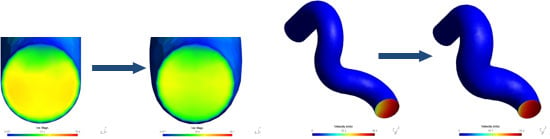
The first case is from the optimization of a pump inlet. The target in this case was velocity uniformity, which was increased by 6%. The original and optimized geometries are presented in the following figures.
The results were also verified with the use of another commercial CFD solver. The improvement is visible in the figures below. The recirculation area is decreased in the optimized shape and also the high speed area after the sharp turn has a smaller width, providing in this way a more uniform outlet. A second industrial example comes from the optimization of a double suction pump inlet. The targets in this case were velocity uniformity improvement and total pressure drop minimization, with a weight of 50% each.
The outlet of the original geometry was suffering from a high virtuosity area, which is illustrated in the next figure. This was severely affecting the outlet profile of this geometry (and therefore the inlet to the impellers that follow). However, the optimization of such a geometry was proving to be diÿcult and based only on trial and error. Even with that, any changes previously explored were not satisfactory.
Once provided with the geometry above, Shaper was able to realize the effect of the vortex, back trace its sensitivity within the flow field and modify the geometry so that the vortex in removed and the velocity uniformity improved. The figure below presents the outlet of the optimized geometry, where it is visible that the vortex was completely removed and now the profile was much more uniform. This improved the performance of the overall pump significantly. The optimized geometry presented a 5.1% improvement in velocity uniformity and a 6.7% in total pressure drop in just seven design iterations, which was a computation of just a few hours. This showcases the amount of design time that can be saved with the use of Shaper.
As mentioned before though, many engineers may just want an indication of where and how to change their designs. Shaper can provide the sensitivity information without changing the shape at all and let the engineer do the modifications according to his experience.
Summary
Shaper is a product by Advanced Design Technology which aims to ease the design and optimization of complex shapes. There are many of the latter that have not been examined for optimization before because that would be computationally too expensive. Complex geometries were improved until now via trial and error, which is also expensive and less eÿ cient. Shaper can help with all those aspects and provide many new novelty designs that will give a competitive advantage.
Watch our webinar Sensitivity Analysis and Optimization of Arbitrarily Complex Geometries using TURBOdesign Shaper. This webinar will introduce TURBOdesign Shaper, a new software product of Advanced Design Technology that targets to ease the design of arbitrarily complex geometrical shapes. It is a unique solution for sensitivity analysis and optimization with computational cost independent of the complexity.
Find out more about how TURBOdesign ShaperTURBOdesign Shaper optimizes complex geometries with respect to given targets, such as total pressure loss and velocity uniformity.
Book a LIVE demo on the design of a turbomachinery application of your choice.
Our demo is tailored to your specific application and design challenges

Share This Post