Across the specific speed range, pumps are subject to various flow phenomena and loss mechanisms which are dominant in that particular range. For example, leakage and secondary flow effects are more dominant in lower ranges, whereas profile losses and corner separation in diffusers take priority in the higher ranges. In this article, we focus on corner separation in vaned diffusers and how to come up with a set of optimal design guidelines to suppress this particular loss mechanism in a pump.
Conventional Design Diffuser Pump
Vaned bowl diffusers are typically used in centrifugal and mixed-flow applications. As Figure 1 shows, they turn the flow essentially from an almost radial to an almost axial direction, which results in quite a complex three-dimensional blade shape leading to these complications:
- This makes it very common for such diffusers to display a strong corner separation, which can be observed in CFD results and is further confirmed through oil flow visualization, as shown in the figure.
- Furthermore, this separation leads to a highly non-uniform flow at the exit of the diffuser, and this, too, has a major adverse effect on the performance of the stage.
Due to the highly complex three-dimensional nature of the flow, the detailed CFD analysis of the baseline conventional stage is used to understand the flow physics, which eventually helps to determine the ideal blade loading that can reduce this exit flow non-uniformity.
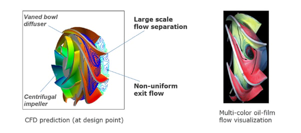
Figure 1: Corner separation in conventional vaned bowl diffuser
Flow Mechanism causing Corner Separation
The CFD results in Figure 2 reveal that the flow separation location corresponds to the region of positive pressure gradient, where the meridional shape shows a bend at the hub. However, although there is a correspondence, a positive pressure gradient by itself does not result in such a big tornado-type corner separation. Hence, stagnation pressure contours are plotted, which reveal a strong accumulation of low momentum fluid at the hub suction surface corner, as shown inside the blue dashed line. In fact, it is this low momentum fluid hitting the strong positive pressure gradient that produces the huge corner separation observed in this case, and understanding this helps determine the optimum blade loading.
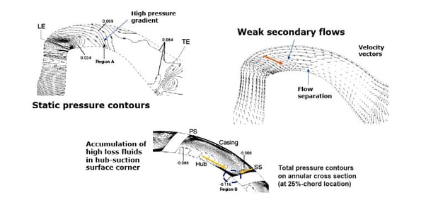
Figure 2: CFD results of conventional vaned bowl diffuser
Optimum Loading for Vaned Diffusers
Figure 2 shows the optimum loading distribution for corner separation control, which has a fore-loaded distribution at the hub and a mid to aft-loaded distribution at the shroud.
- Fore-loading diffuses the flow very rapidly at the hub and therefore removes the region of the high positive pressure gradient. However, since this by itself is not sufficient to eliminate separation, aft-loading at the shroud is also equally crucial.
- Aft-loading at the shroud generates strong secondary flows on the suction surface that move the low-momentum fluid from the shroud wall to the hub wall.
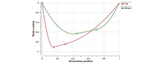
Figure 3: Optimum blade loading for corner separation control in vaned diffusers
Flow Field in Redesigned Diffuser
A flow field analysis of the redesigned diffuser with the optimal set of blade loadings is presented in Figure 4, where the high positive pressure gradient has clearly moved upstream. Furthermore, the intentionally induced secondary flows can be seen to transport the low momentum fluid (that was previously accumulating at the corner of the hub and suction surface) to the middle of the passage, as shown inside the blue dashed line.
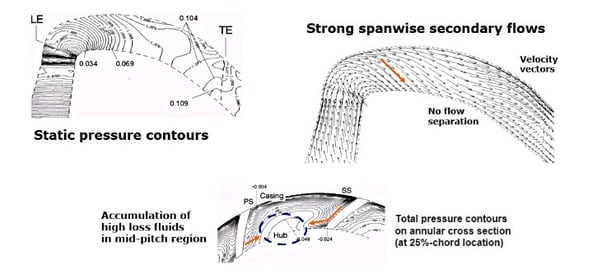
Figure 4: CFD results of inverse-designed diffuser
The net effect of the above changes is complete suppression of the corner separation in the redesigned diffuser, which can be observed in the CFD results and is further confirmed through oil flow visualization, as shown in Figure 5.
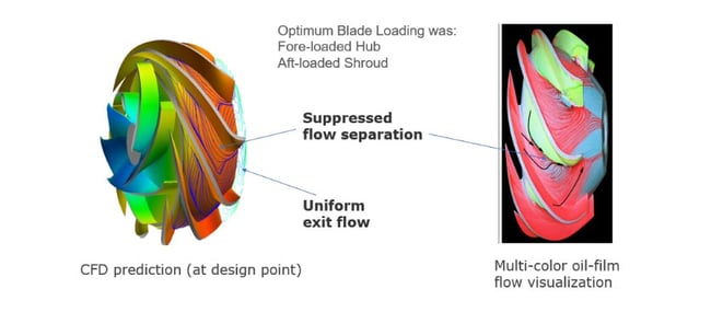
Figure 5: Vaned bowl diffuser with suppressed corner separation
Book a LIVE demo on the design of a turbomachinery application of your choice.
Our demo is tailored to your specific application and design challenges

Share This Post